Custom equipment for precise assembly, controlled handling and consistent production flow.
GMD Engineering develops mechanical designs for bearing and automotive component production—from press-fit stations and part transfer to counting, inspection interfaces and integrated assembly machines.
Engineering Equipment Around the Product and Process
Automotive components and bearings pass through operations that depend on repeatable part location and careful handling. A ring, ball, housing or small assembly may need to be fed, oriented, pressed, measured, counted, marked and transferred before it is ready for the next stage. Each handoff affects the equipment around it.
GMD Engineering designs the mechanical systems that support these operations. We work with manufacturers and equipment builders on individual stations, custom mechanisms and multi-module machines. Our scope can begin with a concept and continue through 3D assemblies, manufacturing drawings and a bill of materials.
The design starts with the actual product: drawings and tolerances, contact surfaces, assembly sequence, process forces, target output, available floor space and interfaces with existing machines. That information determines which mechanisms are appropriate and what must be validated during implementation.
Where We Support Automotive and Bearing Production
Bearing press-fit and assembly stations
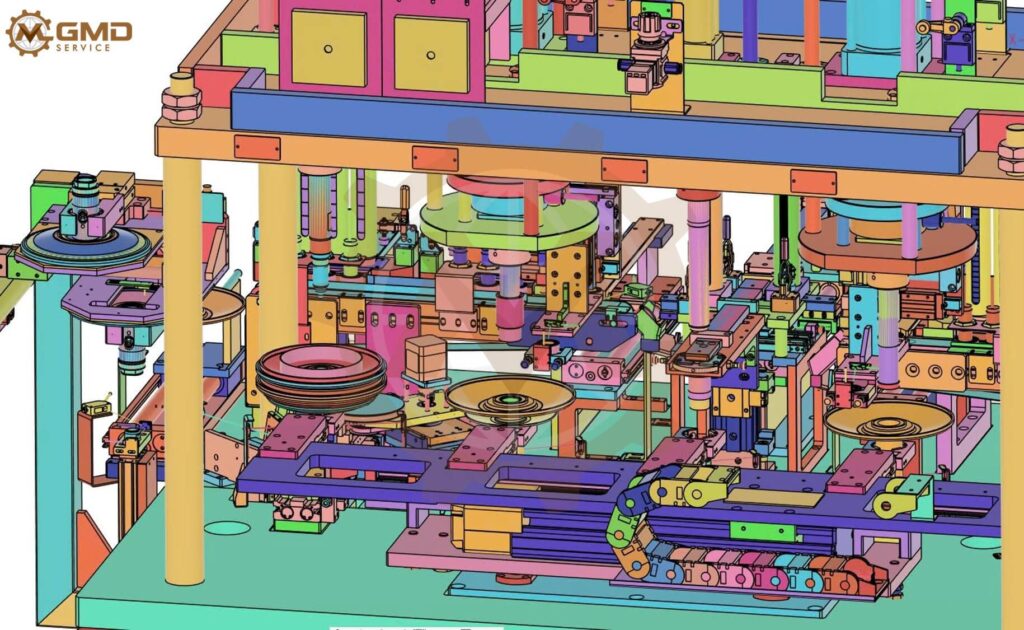
A press-fit operation needs a defined load path and stable part location. Tooling should support the component without damaging functional surfaces or causing misalignment. GMD can design the frame, nests, fixtures, moving mechanisms and mechanical interfaces around the specified process.
We review part datums, insertion direction, required force and stroke, changeover needs and how the assembly is loaded and removed. Press sizing and acceptance limits must be based on the actual component geometry, interference, materials and process requirements.
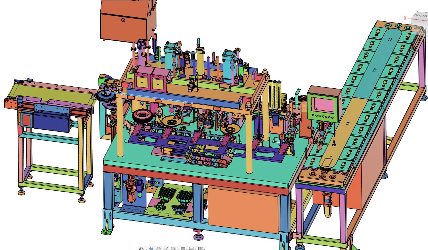
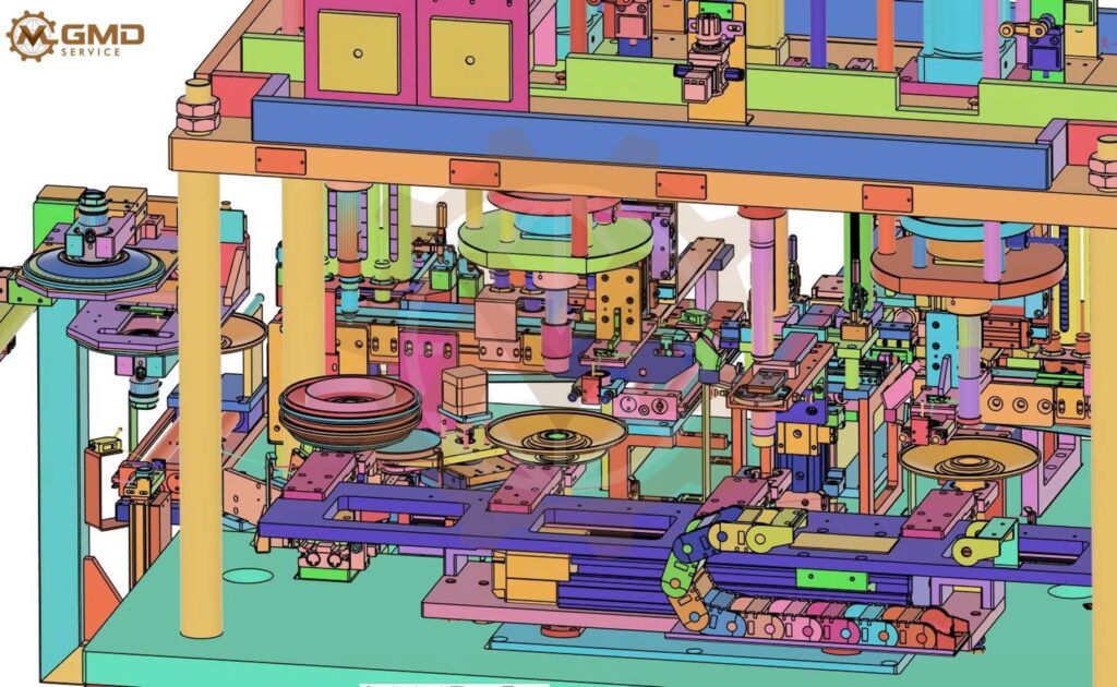
Automatic Bearing Press-Fit and Assembly Machine
Component feeding and orientation
Assembly equipment can only work consistently when components arrive in a predictable condition. We develop mechanical concepts for feeding, singulation, guiding, indexing and orientation. Depending on the part, the solution may use conveyors, guides, pockets, pushers, rotary devices or custom carriers.
The design considers size variants, allowable contact areas, surface finish, risk of jamming and access for clearing a fault.
Transfer between production stations
The movement between pressing, inspection, marking and packing should be designed as part of the overall process. GMD can develop transfer mechanisms, small conveyors, indexing systems and positioning devices that connect operations at the required height and orientation.
For a retrofit, we coordinate the new equipment with the available footprint, machine openings, mounting points and operating sequence.
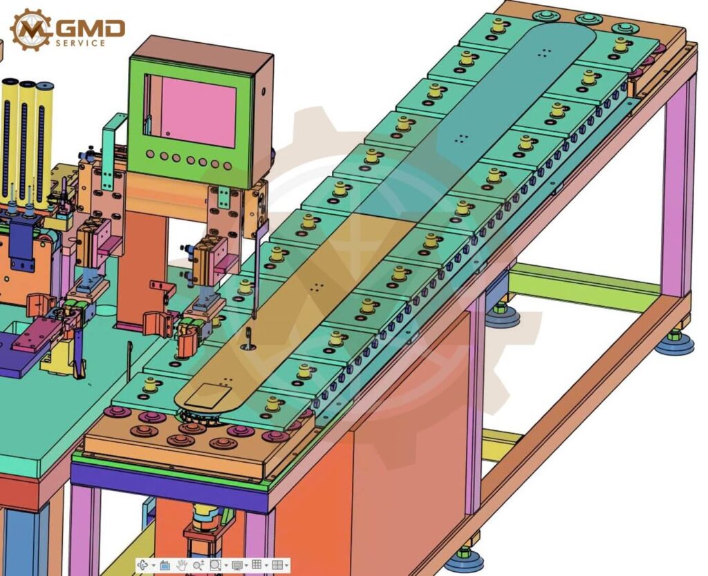
Transfer between production stations
Counting, weighing and demagnetizing equipment
Small components may need to be separated, counted, weighed or routed through a demagnetizing stage. Mechanical design determines how parts reach these devices, remain presented for measurement and move to the next operation.
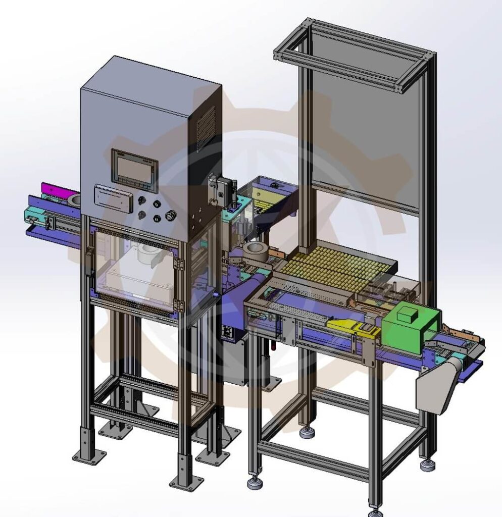
GMD has worked on a bearing-related machine concept with a main plastic conveyor, weighing module, pusher to a scale, camera counting station and demagnetizing module. The machine arrangement illustrates how several operations can be organized into one production flow. Measurement accuracy and demagnetizing results require project-specific hardware, settings and validation.
Bearing Roller Counting, Weighing and Demagnetizing Machine
Inspection and measurement interfaces
An inspection system needs consistent presentation of each part. We can design nests, locating features, indexing mechanisms, sensor and camera mounts, and accepted or rejected part paths. The arrangement should permit access for calibration, cleaning and maintenance.
The inspection method, algorithms, calibration and pass criteria are defined with the responsible inspection specialist unless included in the agreed project scope.
Marking and traceability stations
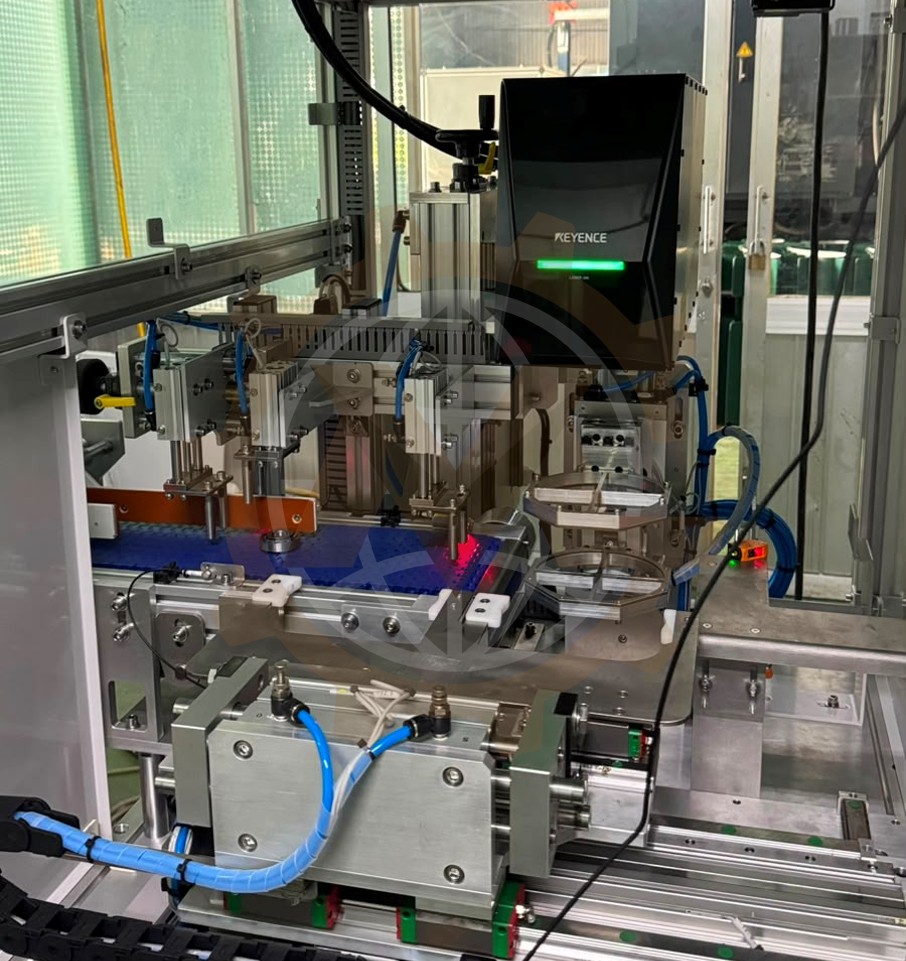
Laser marking and other identification processes depend on repeatable positioning. GMD can design part location and transfer mechanisms around the marking station, with interfaces for the specified equipment and the handling required before and after marking. We have relevant experience with a bearing laser marking machine project.
Automatic Bearing Laser Marking Machine
Fixtures and changeover tooling
Fixtures should locate a product consistently while allowing practical loading, processing and removal. We design nests, supports, stops, clamps and replaceable contact parts around the product drawings and process datums. When several variants share one machine, we define which elements adjust and which require a tooling change.
A press station needs better control of component location or tooling access.
Parts leave one operation in an orientation that does not suit the next.
Small components need a repeatable path through counting and weighing.
A camera needs stable part presentation and a defined reject route.
Several bearing sizes require different fixtures within the same machine envelope.
A new station must fit between existing equipment without blocking maintenance.
An existing machine requires redesigned mechanisms, drawings or BOMs for a new product.
The production team needs a coherent CAD and documentation package for fabrication.
We define the intended outcome and acceptance method for each assignment using the client’s data. Cycle time, accuracy and yield are project requirements to verify, not general promises.
A station may perform only one main operation, but it still has to receive and release a part. For that reason, we review the sequence from incoming material to outgoing product:
How does the component enter the machine?
How is it separated, oriented and located?
Which operation acts on it, and what loads or motion are involved?
How is the result checked or passed to inspection?
Where do accepted and rejected items go?
How does an operator clear a fault or change the product variant?
The answers shape the layout, mechanism selection and interface drawings. They also reveal which responsibilities belong to mechanical design, controls, inspection software, fabrication and commissioning.
Locating surfaces and clamps should follow the component’s functional geometry and agreed datums. Sensitive bearing surfaces need handling methods appropriate to their finish and process state.
Force, stroke and frame stiffness
Pressing and insertion mechanisms need sufficient force and travel, and the surrounding structure must support the defined loads. Relevant calculations or FEA can be included to answer specific design questions when the input conditions are established.
Repeatability and tolerance stack-up
The machine must place the part within the process window. We review sources of variation such as product tolerances, guide clearance, tool adjustment and component wear.
Product variants and changeovers
A shared machine may need adjustable guides or dedicated change parts. A clear variant strategy affects the tooling, BOM, setup instructions and physical access to adjustments.
Service access and production layout
Product flow, operator reach, sensor access, guarding envelope and maintenance space all influence the equipment footprint. We coordinate mechanical interfaces with the facility and neighboring machines.
Inspection and controls interfaces
Mechanical assemblies provide space and mounting for sensors, cameras and actuators. Control logic and inspection performance require their own specifications and verification responsibilities.
How GMD Develops a Project
1. Review components and requirements
We examine product drawings or samples, the process sequence, required output, existing equipment and site constraints. Missing inputs and design assumptions are recorded for review.
2. Develop and compare concepts
We assess practical arrangements for feeding, locating, operating and transferring parts. The concept review focuses on mechanism feasibility, space, access and manufacturing complexity.
3. Detail the mechanical design
We build assemblies and parts in Autodesk Inventor, select suitable mechanical components and address the agreed load and motion questions. Calculations, FEA or motion simulation are used where useful and scoped.
Detail the mechanical design
4. Review interfaces and revisions
We coordinate the design with the client’s production, controls, inspection and manufacturing teams. Agreed feedback is incorporated through controlled revisions.
5. Prepare the engineering handover
The package can include native CAD assemblies, 2D manufacturing drawings, PDF drawing sets, STEP models and a bill of materials. Versions and deliverables are defined before work begins.
Typical Deliverables
Deliverable
Purpose
Machine concept and layout
Review the production sequence, footprint and station arrangement
3D assembly and part models
Coordinate mechanisms and equipment interfaces
Manufacturing drawings
Communicate dimensions and construction details
Assembly and interface drawings
Support integration with neighboring equipment
Bill of materials
Identify manufactured and selected components
STEP and PDF files
Share designs with clients, fabricators and suppliers
The final package depends on whether the project covers concept work, detailed design or modification of existing equipment. Electrical design, PLC programming, vision algorithms, fabrication, site installation and certification are defined separately when needed.
The marking project shows the role of consistent positioning and material flow around a specialized process. Suggested link label: See the Bearing Laser Marking case study.
Add the published URLs after verifying each case study. Use only measurements, cycle times and results that are confirmed and permitted for publication.
Why Work With GMD Engineering?
GMD focuses on the mechanical design of custom machines and production equipment. Our team brings more than 10 years of mechanical design experience and extensive Autodesk Inventor work to concept development, detailed assemblies, manufacturing drawings and BOM preparation.
For automotive and bearing manufacturers, we pay attention to the relationship between stations: part arrival, controlled location, the operation itself, inspection access and transfer onward. We can collaborate remotely with a manufacturer’s engineering team or an equipment builder and prepare the agreed design files for fabrication and integration.
Confidentiality, intellectual property and deliverable requirements can be set out in the project agreement.
Information to Send for a Project Discussion
Product drawings, 3D models, photos or representative samples.
Product variants, dimensions, mass and critical tolerances.
The required operation and complete part flow.
Target output, duty cycle and available production time.
Known press loads, strokes or other process parameters.
Required positioning and inspection criteria.
Existing equipment interfaces, site layout, photos and videos.
Preferred purchased components and manufacturing methods.
Required CAD version, drawings and BOM format.
Applicable customer, safety and validation requirements.
Preliminary data is sufficient for an initial review. We can identify the remaining design inputs together.
Yes. We can develop the mechanical station and tooling arrangement around the component drawings, required operation and agreed loads. The pressing process and final acceptance criteria require project-specific verification.
Can you design equipment for several bearing sizes?
Yes. We can assess adjustable features and replaceable tooling once the product range and changeover requirements are known.
Can you integrate counting, weighing and inspection stations?
We can design the mechanical flow and interfaces connecting these modules. Hardware selection, software, calibration and achieved measurement performance are assigned in the project scope.
Do you support existing production lines?
Yes. A new station or mechanism can be designed around available CAD files, interface drawings, videos and site measurements. A retrofit scope starts with reviewing the installed equipment and its constraints.
Do you manufacture or install the machines?
GMD’s core scope on this page is mechanical design and technical documentation. Fabrication, installation and commissioning responsibilities are agreed for each project.
What files can you deliver?
Depending on scope, we can provide Autodesk Inventor assemblies and parts, STEP files, 2D manufacturing drawings, PDFs and a bill of materials. We confirm the required software version and revision format at project start.
Build Equipment Around Your Production Requirement
Whether you need a bearing assembly station, a component transfer mechanism, an inspection fixture or a multi-module machine, GMD can develop the mechanical design around the product and process you actually run.
Share your component drawings and production sequence to discuss a suitable engineering scope.
We use cookies to make our website work, analyse traffic and improve your experience. You can accept all cookies, deny non-essential cookies or manage your preferences. You can change your choice at any time. For more information, please see our Cookie Policy.
Functional
Always active
The technical storage or access is strictly necessary for the legitimate purpose of enabling the use of a specific service explicitly requested by the subscriber or user, or for the sole purpose of carrying out the transmission of a communication over an electronic communications network.
Preferences
The technical storage or access is necessary for the legitimate purpose of storing preferences that are not requested by the subscriber or user.
Statistics
The technical storage or access that is used exclusively for statistical purposes.The technical storage or access that is used exclusively for anonymous statistical purposes. Without a subpoena, voluntary compliance on the part of your Internet Service Provider, or additional records from a third party, information stored or retrieved for this purpose alone cannot usually be used to identify you.
Marketing
The technical storage or access is required to create user profiles to send advertising, or to track the user on a website or across several websites for similar marketing purposes.