
Automatic Bearing Laser Marking Machine Design
GMD Engineering developed an automatic bearing laser marking machine featuring infeed and outfeed conveyors, product detection, synchronized dual-position transfer, Keyence laser marking, and a 180-degree rotating gripper for marking both sides of each bearing.
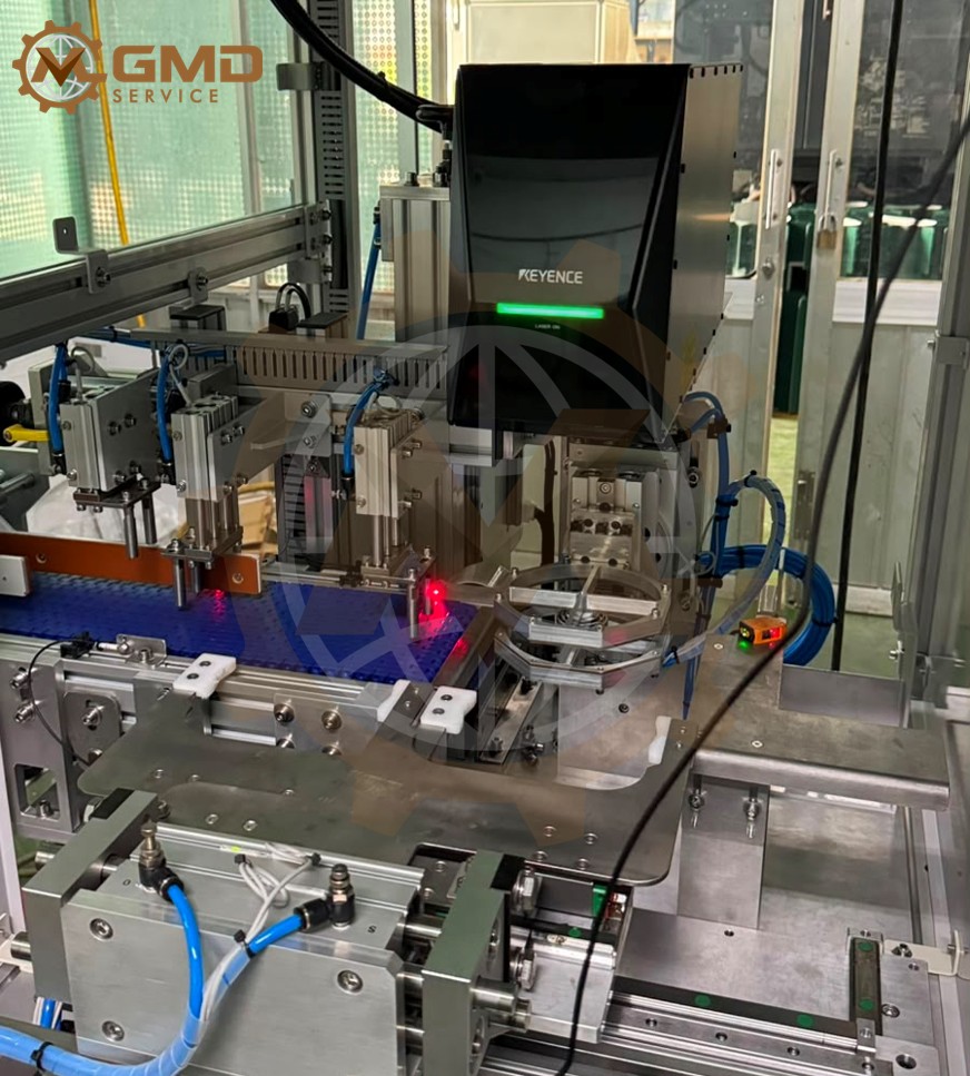
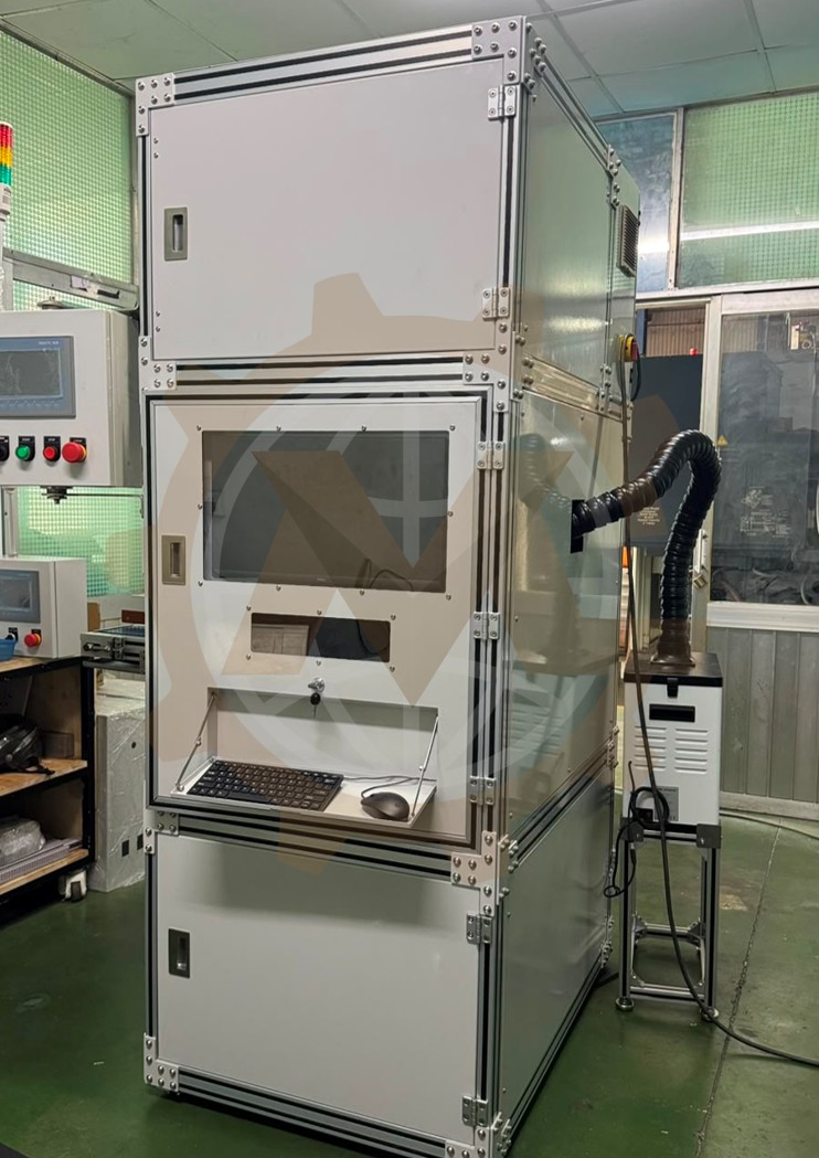
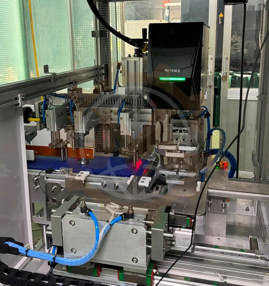
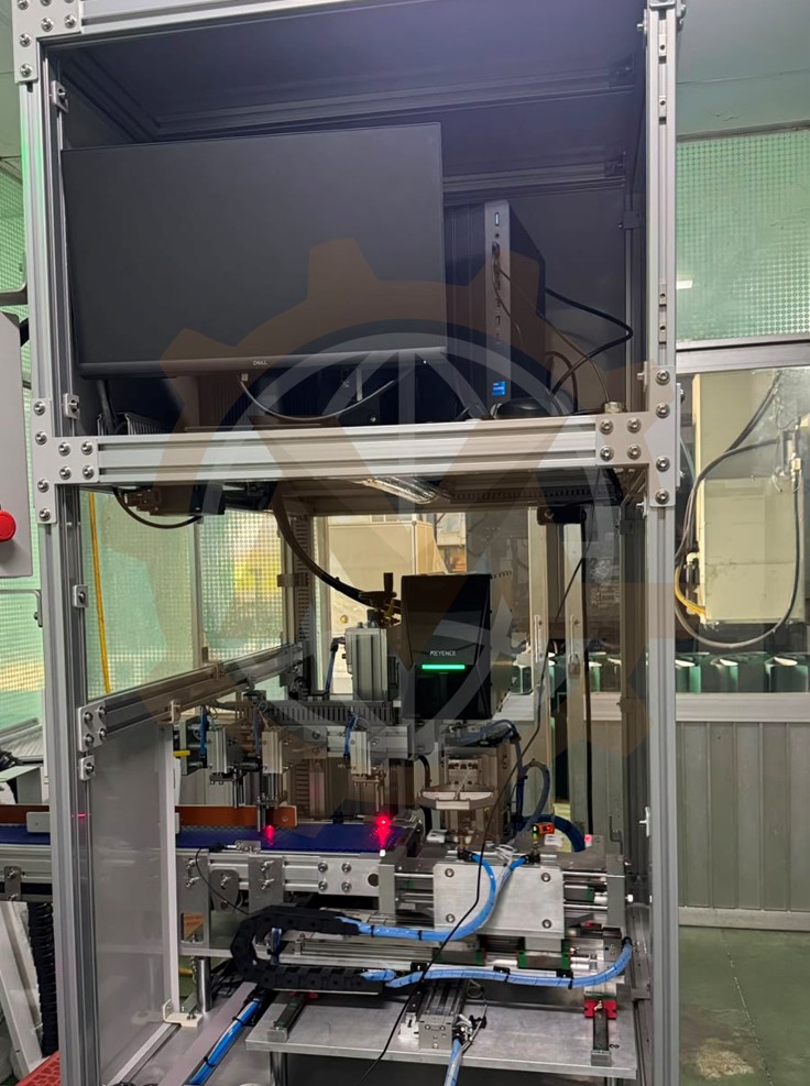
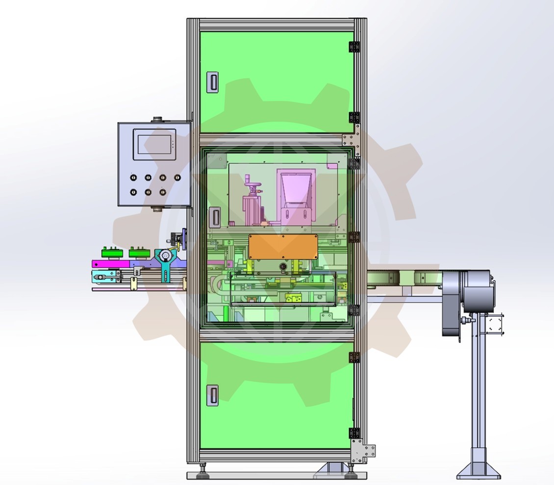
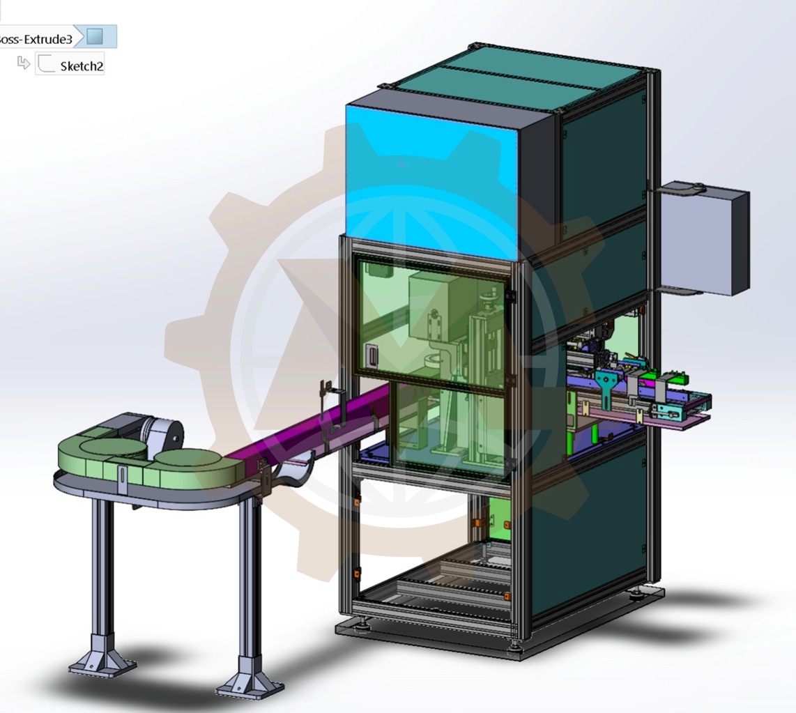
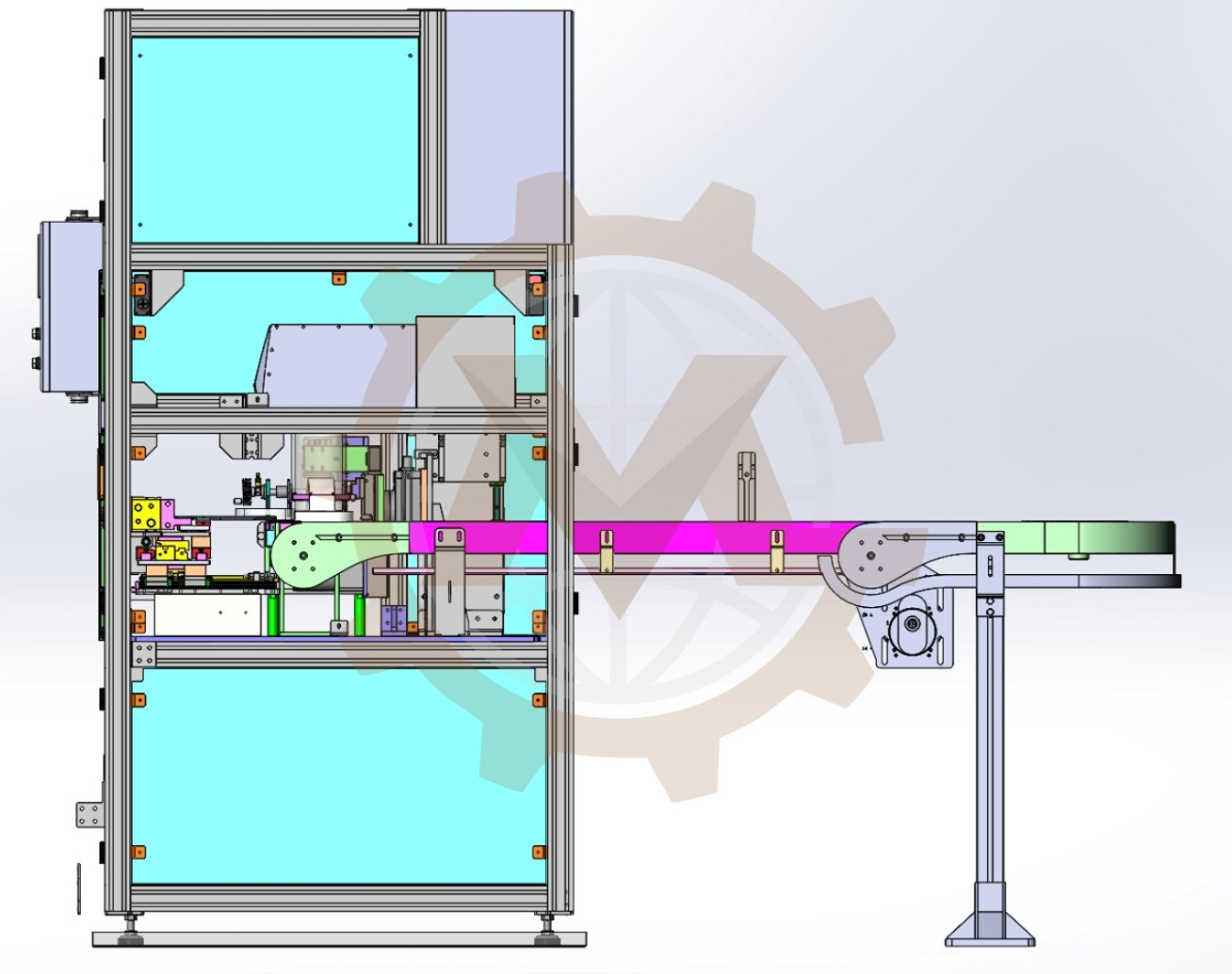
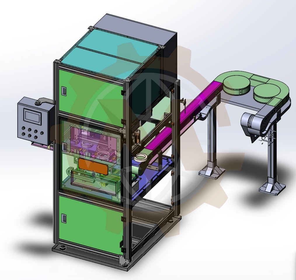
GMD Engineering developed an automatic bearing laser marking machine designed to mark identification information on both sides of a bearing. The machine integrates product conveying, position detection, synchronized pneumatic transfer, laser marking, 180-degree product rotation, and automatic discharge into one compact automation system.
The system uses a Keyence laser marking unit to produce permanent and consistent markings on the bearing surfaces. A synchronized dual-position transfer mechanism simultaneously loads an unmarked bearing into the laser station and transfers the completed bearing to the outfeed conveyor.
This coordinated operation reduces idle time between production cycles, improves product positioning accuracy, and minimizes manual handling.
Automated Bearing Marking System Overview
The customer required an automated solution capable of receiving bearings from an upstream process, marking both sides of each bearing, and transferring the completed products to the next production stage.
The machine needed to perform the following functions:
- Automatically receive bearings from the infeed conveyor.
- Detect when a bearing reaches the transfer position.
- Transfer an unmarked bearing into the laser marking fixture.
- Simultaneously remove a completed bearing from the marking fixture.
- Hold the bearing securely during laser marking.
- Rotate the bearing by 180 degrees.
- Mark both sides of the bearing.
- Transfer the completed bearing to the outfeed conveyor.
- Maintain accurate and repeatable product positioning.
- Minimize the non-productive time between cycles.
Bearing Identification and Automation Requirements
The main objective was to develop a compact and reliable machine that could automate the bearing identification process while maintaining consistent marking position and quality.
The principal engineering requirements included:
- Automatic bearing transportation.
- Accurate detection of product arrival.
- Repeatable positioning under the laser marker.
- Automatic marking on two bearing surfaces.
- Synchronized loading and unloading.
- Controlled 180-degree bearing rotation.
- Compatibility with a Keyence laser marking system.
- Safe separation between the operator and laser working area.
- Easy access for setup, inspection, and maintenance.
Machine Working Process
1. Bearing Infeed Conveyor
Bearings enter the machine through the infeed conveyor. The conveyor transports each bearing toward the pneumatic transfer position.
Mechanical guides maintain the correct bearing path and prevent the product from moving sideways during transportation. The guide width can be designed or adjusted according to the outside diameter of the bearing.
The infeed conveyor also creates a continuous product flow between the previous production process and the laser marking station.
2. Product Position Detection
When a bearing reaches the required transfer position, a sensor detects its presence and sends a confirmation signal to the machine control system.
Before starting the transfer cycle, the PLC verifies that:
- A bearing is present at the infeed position.
- The laser marking process for the previous bearing has been completed.
- The rotating gripper is in the correct transfer position.
- The outfeed position is available.
- All transfer cylinders are in their required starting positions.
This sequence prevents an empty cycle, incorrect transfer, or collision between the moving mechanisms.
3. Synchronized Dual-Position Transfer
The machine uses a synchronized pneumatic transfer assembly that handles two bearings during the same movement.
The transfer mechanism performs two operations simultaneously:
- The first gripper picks up an unmarked bearing from the infeed conveyor and moves it into the laser marking fixture.
- The second gripper removes the completed bearing from the laser marking fixture and transfers it to the outfeed conveyor.
Both grippers are mounted on the same transfer assembly and move together between the infeed, laser marking, and outfeed positions.
This synchronized arrangement allows one finished bearing to be unloaded while the next bearing is loaded. It reduces unnecessary return movements and shortens the overall machine cycle time.
4. Bearing Clamping and Positioning
After the new bearing reaches the marking station, the positioning mechanism locates and secures it beneath the laser marking head.
Accurate product positioning is essential because any movement or angular variation can affect the marking location and readability.
The fixture is designed to:
- Center the bearing relative to the laser marking area.
- Hold the bearing securely during marking.
- Maintain a repeatable distance between the bearing surface and laser head.
- Allow the bearing to rotate without losing its reference position.
- Release the bearing automatically after marking is completed.
The clamping force must be sufficient to hold the bearing securely without damaging its surface.
5. First-Side Keyence Laser Marking
Once the bearing has been correctly positioned and clamped, the Keyence laser marking system marks the first side.
Depending on the production requirements, the laser can apply information such as:
- Part numbers.
- Serial numbers.
- Batch or lot numbers.
- Manufacturing dates.
- Company logos.
- Product specifications.
- Traceability codes.
- Data Matrix or QR codes.
The marking parameters can be configured according to the bearing material, surface finish, marking depth, contrast requirements, and required cycle time.
6. Automatic 180-Degree Rotation
After the first side has been marked, the rotating gripper turns the bearing by 180 degrees.
The rotation mechanism maintains control of the bearing throughout the movement, ensuring that the product remains correctly located relative to the laser marking head.
Once the 180-degree rotation is complete, position sensors confirm that the mechanism has reached the correct orientation before the second marking cycle begins.
This automatic rotation eliminates the need for an operator to manually remove, flip, and reposition the bearing.
7. Second-Side Laser Marking
After rotation, the opposite side of the bearing is positioned beneath the Keyence laser marker.
The laser system then applies the required identification information to the second surface. The information can be identical to or different from the marking on the first side, depending on the customer’s traceability requirements.
The bearing remains securely clamped until the second marking operation has been completed.
8. Transfer to the Outfeed Conveyor
When both sides have been successfully marked, the rotating fixture returns to its transfer position and releases the bearing to the synchronized transfer gripper.
During the next transfer cycle:
- The completed bearing moves from the laser station to the outfeed conveyor.
- A new bearing moves from the infeed conveyor into the laser station.
The outfeed conveyor then transports the finished bearing out of the machine and toward the next production process or collection area.
Main Machine Components
Infeed Conveyor Assembly
The infeed conveyor automatically transports bearings from the previous process to the product detection and transfer position.
Its main components include:
- Conveyor belt.
- Drive motor.
- Adjustable side guides.
- Bearing stop and positioning components.
- Product presence sensor.
- Supporting frame.
Product Detection System
The detection sensor confirms that a bearing has arrived at the correct transfer location. Its signal is used as an interlock within the automated machine sequence.
The sensor mounting position is designed to provide reliable detection while remaining accessible for adjustment and maintenance.
Dual-Gripper Transfer Mechanism
The transfer mechanism uses two gripping positions to load and unload bearings simultaneously.
The assembly includes:
- Horizontal pneumatic transfer cylinder.
- Vertical lifting or gripping cylinders.
- Two bearing grippers.
- Linear guides.
- Cylinder position sensors.
- Mechanical stroke adjustment.
- Cable and pneumatic tube management.
The dual-position design is one of the key features that improves the machine’s production efficiency.
Keyence Laser Marking Unit
The Keyence laser marker creates permanent identification marks on both bearing surfaces.
The laser marking unit is mounted on an adjustable support structure, allowing the working distance and marking position to be set accurately.
The laser system communicates with the machine controller to receive marking commands and return status signals such as:
- Ready.
- Marking in progress.
- Marking completed.
- Fault or alarm condition.
Bearing Clamping Fixture
The bearing fixture accurately locates and holds the product during marking. Its design is based on the bearing diameter, width, contact surfaces, and required marking position.
Interchangeable or adjustable tooling can be incorporated if the machine needs to process multiple bearing sizes.
180-Degree Rotating Gripper
The rotating gripper turns the bearing between the first and second laser marking operations.
The mechanism includes:
- Pneumatic rotary actuator or equivalent rotary drive.
- Bearing clamping jaws.
- Rotation position sensors.
- Mechanical rotation stops.
- Adjustable product locating elements.
The rotation is completed automatically within the guarded laser marking area.
Outfeed Conveyor Assembly
After marking, the completed bearing is placed onto the outfeed conveyor. The conveyor transfers the product away from the laser station and can connect directly to another machine or downstream inspection process.
Automation and Control Sequence
The complete operating sequence can be controlled by a PLC and coordinated with the Keyence laser marker.
A typical automatic cycle includes:
- The infeed conveyor transports a bearing into the machine.
- The product sensor confirms that the bearing has reached the transfer position.
- The PLC verifies that the laser station and outfeed position are available.
- The synchronized transfer grippers pick up the incoming and completed bearings.
- The transfer cylinder moves both bearings to their next positions.
- The incoming bearing is placed into the laser marking fixture.
- The completed bearing is placed onto the outfeed conveyor.
- The fixture clamps and accurately positions the incoming bearing.
- The Keyence laser marks the first side.
- The rotating gripper turns the bearing by 180 degrees.
- The Keyence laser marks the second side.
- The rotating fixture returns to the transfer orientation.
- The machine confirms completion and prepares for the next cycle.
The PLC can also monitor sensor signals, cylinder positions, marking status, production quantities, alarms, and machine safety conditions.
Key Engineering Challenges
Accurate Bearing Positioning
The bearing must be placed consistently within the laser marking area. Even a small positional or angular variation may cause the marking to shift from its specified location.
The fixture and gripping mechanisms were designed to establish repeatable locating references throughout the transfer, clamping, and rotating operations.
Synchronizing Two Transfer Operations
The loading and unloading grippers move together and must complete their actions without colliding with the fixture, conveyor, or rotating mechanism.
The motion sequence, cylinder strokes, product clearances, and sensor interlocks were carefully coordinated to ensure reliable operation.
Maintaining Position During Rotation
The bearing must remain firmly held while rotating through 180 degrees. The rotating gripper must prevent slipping while avoiding excessive clamping force that could damage the product surface.
Consistent Laser Working Distance
Laser marking quality depends on maintaining the correct focal distance between the laser head and the bearing surface.
The machine structure and fixture were designed to maintain a stable and repeatable marking height for each production cycle.
Reducing Machine Cycle Time
The synchronized dual-position transfer system allows loading and unloading to occur during the same movement. This minimizes non-productive transfer time and helps increase overall machine throughput.
Safety Considerations
The machine integrates automated pneumatic movements and an industrial laser marking system. Appropriate safety measures are therefore required.
Typical safety features include:
- Fully enclosed laser marking area.
- Safety-interlocked access doors.
- Laser-safe protective panels or viewing windows.
- Emergency stop push buttons.
- Cylinder position sensors.
- Product presence detection.
- Pneumatic pressure monitoring.
- Motion sequence interlocks.
- Controlled restart after an emergency stop.
- Alarm indication through the HMI.
- Extraction connection for smoke or marking fumes where required.
The final safety system must be selected based on a formal risk assessment and the regulations applicable at the installation location.
Project Results
The completed machine automates the entire bearing laser marking process, from product arrival to two-sided marking and discharge.
The design provides several operational benefits:
- Automatic bearing loading and unloading.
- Permanent marking on both bearing surfaces.
- Accurate and repeatable marking positions.
- Synchronized transfer of two products.
- Reduced transfer and waiting time.
- Lower manual handling requirements.
- Improved production consistency.
- Better product traceability.
- Compact machine footprint.
- Easy integration with an existing production line.
- Potential compatibility with multiple bearing sizes through interchangeable tooling.
Engineering Services Provided
GMD Engineering’s mechanical design scope for this project included:
- Machine concept development.
- 3D mechanical design.
- Infeed and outfeed conveyor design.
- Dual-position pneumatic transfer mechanism design.
- Bearing gripping and positioning fixture design.
- 180-degree rotating mechanism design.
- Keyence laser marker integration.
- Machine frame and guarding design.
- Pneumatic component arrangement.
- Sensor mounting design.
- Design for manufacturing and assembly.
- Detailed 2D manufacturing drawings.
- Assembly drawings.
- Bill of Materials preparation.
Custom Laser Marking Machine Design Services
GMD Engineering provides custom machine design and industrial automation engineering services for machine builders, manufacturers, and engineering companies worldwide.
Our capabilities include:
- Automatic laser marking machine design.
- Product traceability systems.
- Bearing handling and assembly machines.
- Pneumatic pick-and-place mechanisms.
- Custom gripping and positioning fixtures.
- Rotary product handling systems.
- Conveyor system design.
- Automatic inspection machines.
- Assembly machine design.
- Production line integration.
- 3D CAD modeling.
- 2D manufacturing drawings.
- Bill of Materials development.
- Motion simulation and mechanism verification.
Each system is developed according to the customer’s product geometry, marking requirements, target cycle time, factory layout, automation level, and safety requirements.
Looking for an Automatic Laser Marking Solution?
If you need to automate the marking, identification, handling, or traceability of bearings and other industrial components, GMD Engineering can support your project from initial concept development through detailed mechanical design and manufacturing documentation.
Contact us to discuss your product dimensions, marking content, required cycle time, laser system, production capacity, and line integration requirements.
Need a Custom Laser Marking Machine?
Contact GMD Engineering to discuss your automatic laser marking, product handling, or industrial traceability machine project.