Engineering Support for Metal Fabrication Operations
Metal fabrication involves more than cutting, bending, welding or machining. Sheets, plates, profiles and finished components must also be loaded, positioned, transferred, lifted, accumulated and delivered to the next operation. If the handling equipment does not match the process, operators lose time, machines wait for material and heavy components become difficult to manage safely.
GMD Engineering supports metal fabricators, steel processors and equipment builders with mechanical design for the systems around those production steps. Our work can cover an individual lifting device or fixture, a conveyor between processes, or the mechanical layout of a larger automated line. We develop design concepts around the actual workpiece, available floor space, production sequence, access requirements and intended fabrication methods.
Our service is engineering design and technical documentation. Fabrication, installation, electrical controls and certification can be defined separately for each project.
Where Mechanical Design Makes a Difference
Sheet and Plate Loading and Unloading
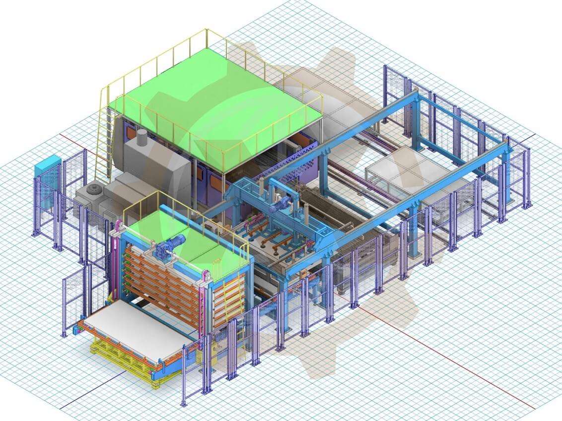
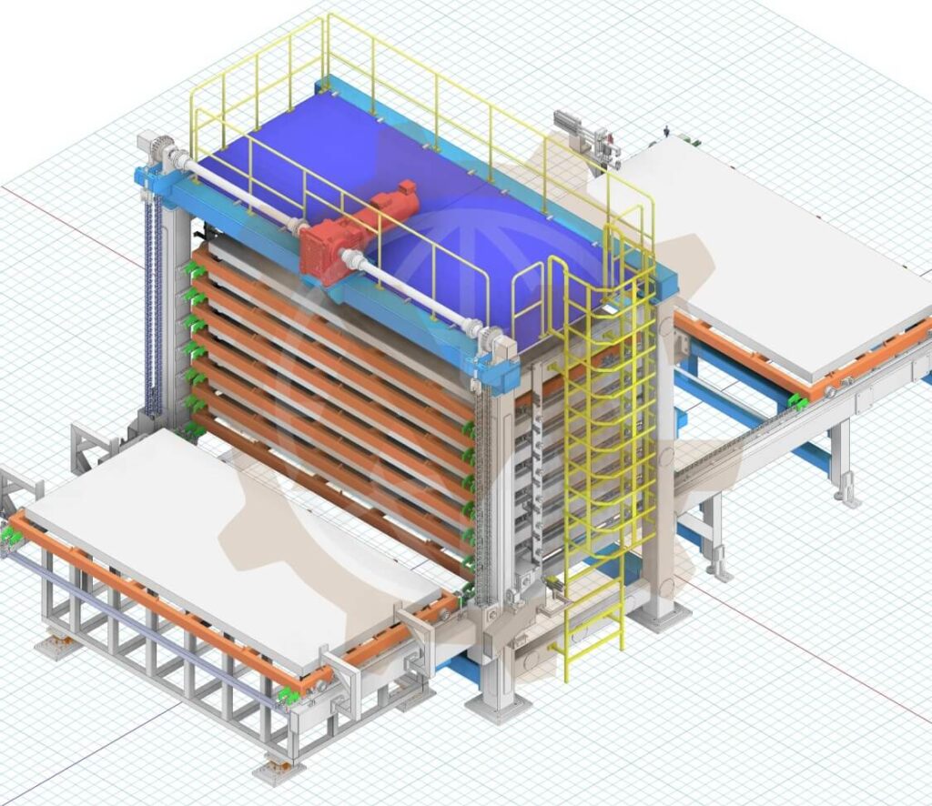
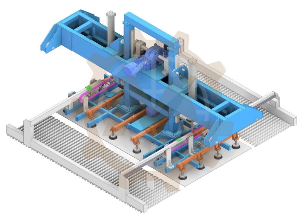
Large sheets and heavy plates require reliable pickup, clearance around equipment and controlled placement. We can develop mechanical concepts for loading and unloading laser cutters and other processing machines, including lift frames, vacuum handling arrangements, transfer paths, guides, stops and interfaces with existing equipment. The design considers material dimensions, mass, surface condition, stacking format, cycle sequence and access for operators and maintenance.
Sheet and Plate Loading and Unloading
Steel Material Transfer and Conveying
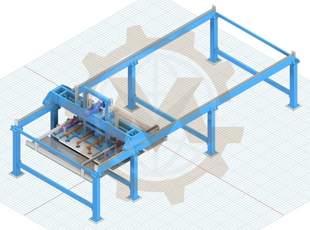
Conveyors and transfer devices can connect storage, cutting, inspection and downstream processing. Depending on the workpiece and process, the solution may use roller conveyors, chain conveyors, powered transfer stations, positioning devices or custom handling mechanisms. We define the layout and mechanical interfaces so that material flows through the facility with appropriate support and clearance.
Steel Material Transfer and Conveying
Lifting and Positioning
Steel components can be awkward to lift even when their nominal mass appears manageable. Custom lifting equipment and positioning mechanisms can help move a workpiece between machines or present it at a useful working height. Design inputs include load cases, center of gravity, gripping method, travel, reach, duty cycle and failure scenarios. Applicable standards and any required verification should be identified at the start of the project.
Lifting and Positioning
Fixtures, Jigs and Production Aids
Repeatable positioning matters in welding, assembly, drilling and inspection. We can design fixtures, locating features, clamps and support frames around part geometry, tolerance requirements and operator access. The goal is to make loading straightforward, hold the component where the process needs it and allow practical manufacturing and maintenance of the fixture itself.
Custom Machines and Line Integration
Some fabrication challenges need a purpose-built machine rather than a standard catalog product. GMD can develop mechanical concepts for feeding, orienting, indexing, separating, transferring or presenting workpieces. When a machine interfaces with other equipment, we document mounting envelopes, transfer heights, service access and mechanical handoff points for integration with the broader line.
Typical Challenges We Help Address
- Moving sheets or plates between storage, cutting and downstream processes.
- Loading a laser cutting machine while preserving operator and service access.
- Supporting long profiles or heavy parts without uncontrolled movement or excessive deflection.
- Designing a transfer route within limited floor space and existing machine clearances.
- Improving the repeatability of part location during welding, machining or inspection.
- Reducing manual handling through suitable mechanical aids and process layout.
- Updating an existing design when workpiece size, throughput or equipment interfaces change.
- Preparing consistent CAD assemblies, drawings and BOMs for the manufacturing team.
These are project situations, not guaranteed outcomes. The final performance targets and acceptance criteria are agreed from the actual process data.
Equipment and Systems We Can Design
| Production need |
Example engineering scope |
| Sheet or plate handling |
Loading frames, vacuum lifting concepts, guides, transfer mechanisms and storage interfaces |
| Material transfer |
Roller and chain conveyors, cross transfers, supports, stops and positioning units |
| Machine loading |
Mechanical interfaces for laser cutting and other fabrication equipment |
| Heavy component lifting |
Custom lifting mechanisms, frames and mechanical handling aids |
| Welding and assembly |
Locating fixtures, clamps, supports and ergonomic production aids |
| Production integration |
Equipment layout, mounting interfaces, access envelopes and mechanical line coordination |
The suitable mechanism depends on material size and condition, load, required accuracy, cycle time, available utilities and the intended operating environment.
Our Engineering Approach
1. Define the Process and Workpiece
We start with the material and the production sequence: dimensions, mass, thickness range, surface condition, edge quality, stack arrangement, throughput, machine interfaces and available space. We also identify how operators load, unload, clean and maintain the equipment.
2. Develop and Review Concepts
We compare relevant mechanical arrangements against the required travel, footprint, access and manufacturing complexity. A concept review helps select a workable approach before detailed CAD work begins.
3. Check Critical Mechanical Requirements
Depending on the scope, we evaluate loads, drive requirements, deflection, stability, gripping forces, component selection and motion. FEA or motion simulation can support selected questions when their inputs and acceptance criteria are clearly defined. Formal validation, safety assessment and certification are scoped separately where needed.
4. Build the Detailed CAD Model
We develop assemblies and parts in Autodesk Inventor, with interfaces and construction details coordinated for fabrication and assembly. The design can be reviewed against the facility layout and neighboring equipment.
5. Prepare Production Documentation
The agreed deliverables may include native CAD files, STEP models, 2D manufacturing drawings, PDF drawing sets and a bill of materials. We define the revision and handover format at the start so the output fits your team’s workflow.
Design Inputs That Help Us Scope Your Project
Share whatever you have available; preliminary data is sufficient for an initial discussion.
- Workpiece drawings or representative dimensions, thicknesses and weights.
- Material type, surface finish and any handling restrictions.
- Current process flow, target sequence and approximate production rate.
- Machine models, interface drawings, transfer heights and utility constraints.
- Site layout, available footprint, access zones and photos or videos of the operation.
- Required accuracy, travel, duty cycle and maintenance preferences.
- Applicable safety requirements, local regulations and required documentation.
- Existing CAD files, component preferences and fabrication capabilities.
Deliverables Matched to Your Manufacturing Workflow
Our mechanical engineering handover can include:
- 3D assemblies and individual part models.
- 2D part and assembly drawings for manufacturing and installation planning.
- Bills of materials and selected component information.
- STEP files and PDF documentation for collaboration with suppliers.
- Concept layouts, interface drawings and design review revisions where included in scope.
The exact package depends on whether you need concept development, detailed design, modification of existing equipment or drawing production. Electrical design, PLC programming, site installation, fabrication and statutory certification are included only if specifically agreed.
Related Project: Sheet Metal Laser Loading and Unloading System
See how a project for a sheet metal laser workflow is presented in GMD’s portfolio. The case study provides a more concrete starting point for discussing machine interfaces, material flow and the engineering documentation needed for a similar system.
View the Sheet Metal Laser Loading and Unloading System case study.
Why Work With GMD Engineering?
GMD focuses on practical mechanical design for custom machines and production equipment. Our team has more than 10 years of mechanical design experience and works extensively with Autodesk Inventor. We collaborate remotely with clients and manufacturing teams, preparing the CAD models, drawings and BOMs needed to review and build the agreed design. Confidentiality and IP requirements can be addressed in the project agreement.
For projects involving steel or sheet metal processing, we focus on the mechanical details that make a concept usable: realistic workpiece handling, fit within the production layout, access for operators, assembly logic and clear handover documentation.
Frequently Asked Questions
Do you manufacture steel processing machines?
GMD provides mechanical engineering design and documentation. Manufacturing or installation is arranged according to the agreed project scope and the client’s supply chain.
Can you design equipment around an existing laser cutting machine?
Yes, a design can be developed around an existing machine when its interface data, operating sequence, clearances and any access or safety constraints are available for review.
Can you modify an existing conveyor or handling system?
Yes. We can review existing models, drawings or site information and define a modification scope. The feasibility depends on the available information and the condition of the installed equipment.
Do you provide vacuum lifting design for steel sheets?
Vacuum handling can be considered when the material surface, load, gripping conditions and operating environment support it. Cup selection, vacuum generation, monitoring, retained load behavior and applicable safety requirements need project-specific assessment.
What information do you need for a quotation?
Send a short process description, representative workpiece data, target operation, layout or machine interfaces, preferred deliverables and any deadline. Drawings, photos and videos help us define the scope more accurately.
Can your team deliver Autodesk Inventor files and manufacturing drawings?
Yes. We can agree on the required Inventor version and the drawing, BOM, PDF and STEP deliverables before work starts.
Plan Your Next Metal Fabrication Equipment Project
Whether you need a sheet loading concept, a steel transfer system, a lifting mechanism or a production fixture, we can help define the mechanical solution and prepare a clear engineering handover.
Tell us what you need to move, lift or position, and share your workpiece and process requirements. Start a project discussion.