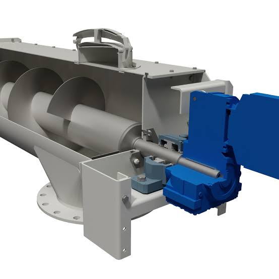
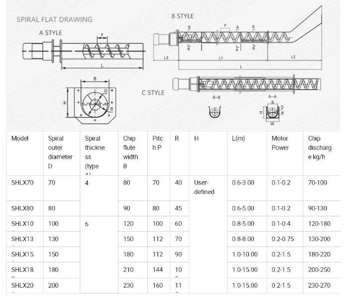
Every screw conveyor behaves differently because flowability, bulk density, moisture, particle size, abrasiveness, temperature, and tendency to pack or smear directly affect capacity, torque, wear, and reliability. Our design approach connects material characteristics with conveyor geometry, speed, trough loading, flight configuration, drive selection, shaft and bearing design, sealing, guarding, and maintenance access—creating a system that is suitable for manufacturing and integration into the complete process line.
Custom Engineering for Reliable Bulk Material Transfer
A screw conveyor appears simple: a rotating helical flight moves material through a trough or tube. In practice, many failures begin when a conveyor is selected only by diameter and nominal capacity. The machine may start empty but stall when loaded, deliver inconsistent feed, compact sensitive material, overload hanger bearings, wear through the trough, leak dust at shaft seals, or bridge beneath the inlet.
GMD Services supports manufacturers, process-equipment builders, system integrators, and industrial plants with custom screw conveyor engineering. The scope can include application review, screw type selection, capacity and power calculations, inlet and discharge development, shaft and flight design, trough or casing design, bearings and seals, drive arrangement, structural supports, guarding, sensors, 3D CAD, detailed drawings, BOMs, and design-review support.
What Is a Screw Conveyor?
A screw conveyor—also called an auger conveyor—uses a rotating helical screw inside a trough or pipe to move bulk material. Material advances because the flight applies axial force while the casing limits rotation of the bulk solids. Conveyors may operate horizontally, on an incline, vertically, or as feeders beneath bins and hoppers.
The same basic principle can be adapted for conveying, metering, mixing, blending, cooling, heating, drying, dewatering, compacting, or distributing material to several outlets. The correct design depends on the intended process function as well as conveying capacity.
Screw Conveyor Configurations We Design
Horizontal Trough Screw Conveyors
Horizontal screw conveyors are widely used for controlled bulk transfer over short to moderate distances. U-trough construction provides access for inspection and cleaning, while tubular or pipe screw conveyors offer better enclosure. Capacity is determined by screw diameter, pitch, rotational speed, trough loading, material factor, and inlet conditions.
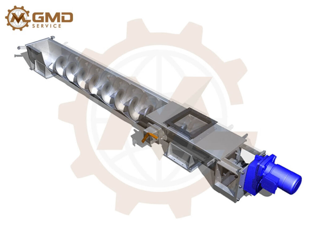
Horizontal Trough Screw Conveyors
Inclined Screw Conveyors
An inclined screw conveyor requires more power and normally delivers less capacity than a comparable horizontal unit because material tends to fall back and circulate. The effect becomes more significant as the angle increases. Design may require a larger diameter, reduced pitch, tubular casing, modified inlet, higher speed, or alternative conveying technology.
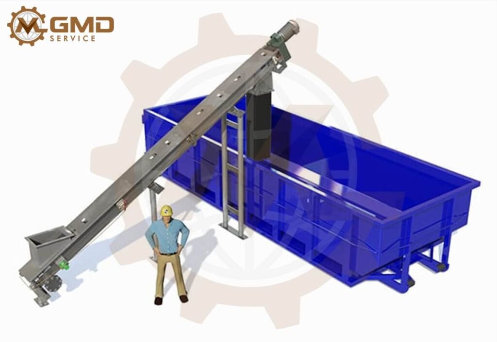
Inclined Screw Conveyors
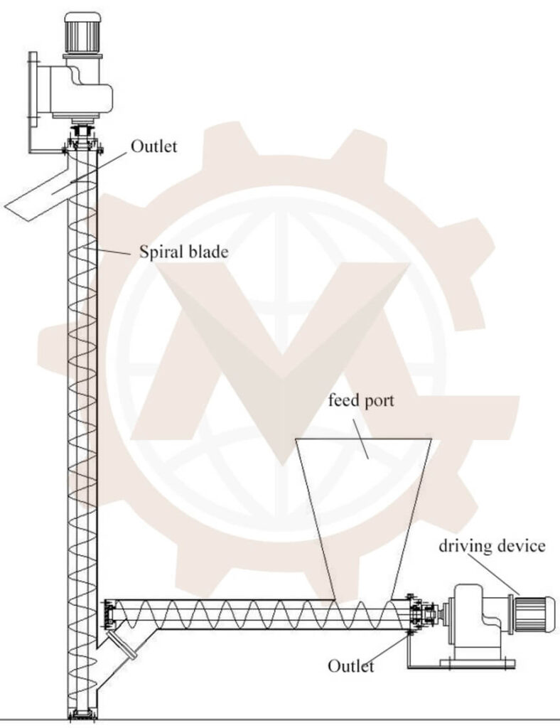
Vertical Screw Conveyors
Vertical screw conveyors use higher rotational speed and controlled feed to elevate material. Stable performance depends on the material entering at a predictable rate and developing the required centrifugal behavior. Starting under load, inlet design, drive power, balance, containment, and discharge control require special attention.
Vertical Screw Conveyors
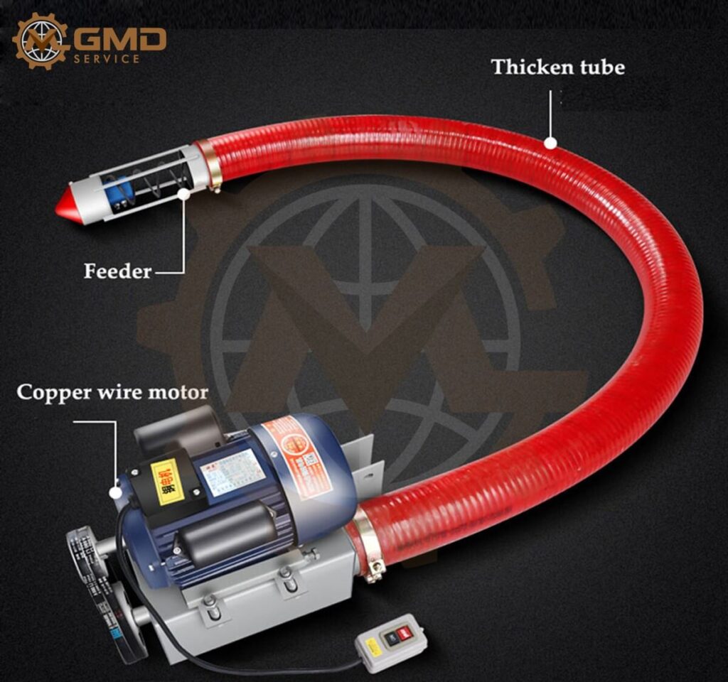
Flexible Screw Conveyors
A flexible screw conveyor uses a flexible spiral rotating inside a polymer or metal tube. It can provide a simple route around obstacles and is often used for powders, granules, and pellets. Selection depends on material flowability, bend radius, tube length, spiral geometry, speed, product degradation limits, cleanout, and the ability to run empty without excessive wear.
Flexible Screw Conveyors
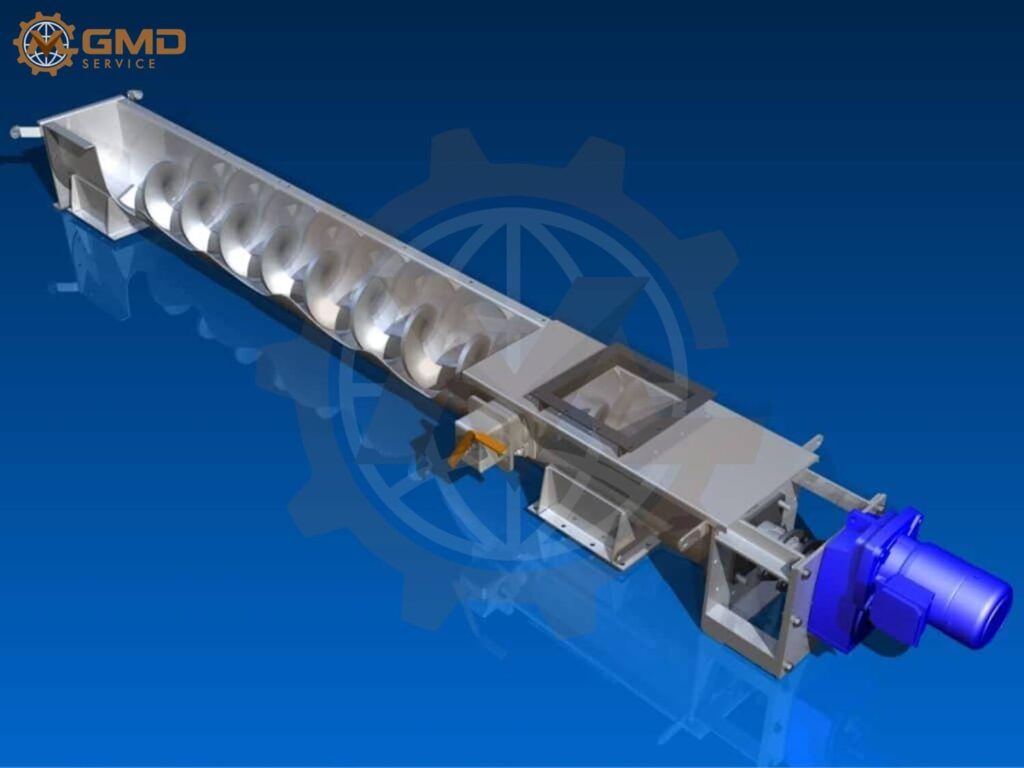
Shaftless Screw Conveyors
A shaftless screw conveyor removes the central pipe and hanger bearings from the material path. It is commonly used for sticky, fibrous, irregular, or wet materials such as screenings, sludge, waste, and dewatered biosolids. The spiral is supported by liners, so liner material, wear rate, drive torque, trough shape, and replacement method are critical.
Shaftless Screw Conveyors
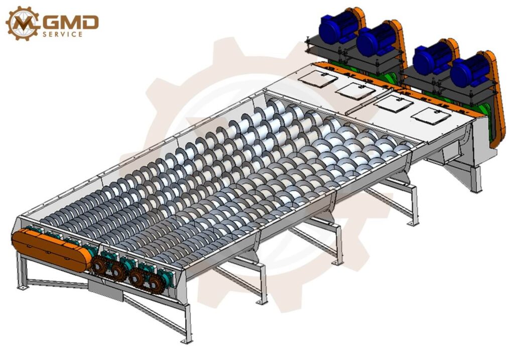
Screw Feeders and Metering Conveyors
A screw feeder controls material withdrawal from a hopper or bin and therefore operates under different loading conditions from a transfer conveyor. Inlet length, variable pitch, tapered shaft, stepped diameter, live-bottom arrangement, and hopper interface can be used to promote mass flow and reduce preferential withdrawal. A feeder should be sized from the required controlled rate and bin behavior, not simply downstream conveyor capacity.
Screw Feeders and Metering Conveyors
Tubular, Sanitary, and Stainless Steel Screw Conveyors
Tubular screw conveyors provide enclosed handling, while stainless steel and sanitary screw conveyors may be used where corrosion resistance, cleanability, surface finish, contamination control, or washdown is important. Hygienic details, removable components, drainability, seals, weld finish, and validation requirements must be agreed for each application.
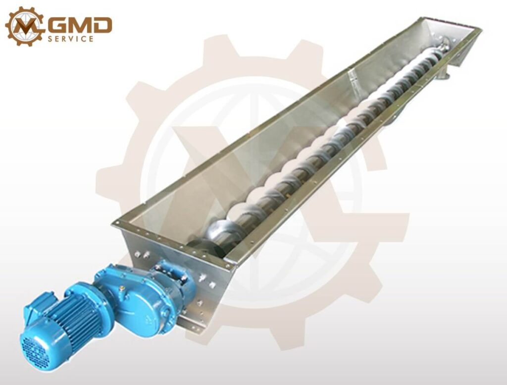
Tubular, Sanitary, and Stainless Steel Screw Conveyors
Process Screws for Mixing and Heat Transfer
Ribbon, paddle, cut-flight, interrupted-flight, twin-screw, jacketed, hollow-flight, heated, cooled, and thermal screw conveyors can combine transport with mixing or heat transfer. These machines require process data beyond conventional conveying calculations, including residence time, heat duty, product sensitivity, mixing objective, fouling, and cleanout requirements.
|
Configuration
|
Typical application
|
Critical design focus
|
|
Horizontal trough screw
|
General bulk transfer
|
Capacity, trough loading, bearings, access and dust control
|
|
Inclined screw
|
Elevation with a compact footprint
|
Capacity loss, fallback, inlet behavior and increased power
|
|
Vertical screw
|
Steep or vertical elevation
|
Controlled feed, speed, starting torque, balance and containment
|
|
Flexible screw
|
Powders and granules on flexible routes
|
Spiral/tube selection, bend radius, degradation and cleanout
|
|
Shaftless screw
|
Sludge, waste, sticky or fibrous material
|
Torque, liner wear, trough geometry and discharge behavior
|
|
Screw feeder
|
Controlled hopper withdrawal
|
Flood loading, mass-flow pattern, pitch/shaft variation and metering
|
|
Process screw
|
Mixing, heating, cooling or drying
|
Residence time, heat transfer, fouling and product quality
|
Material Data Comes Before Conveyor Geometry
Screw conveyor design begins with representative material data. A description such as “powder” or “sludge” is not enough because two materials with similar bulk density can behave very differently inside the same screw.
- Bulk density under realistic operating conditions, including loose and compacted values where relevant.
- Particle size distribution, particle shape, lump size, and the presence of foreign objects.
- Flowability, internal friction, wall friction, bridging, ratholing, flooding, or flushing behavior.
- Moisture content, stickiness, cohesiveness, compressibility, aeration, and tendency to smear or cake.
- Abrasiveness, corrosiveness, temperature, ignition sensitivity, toxicity, and dust characteristics.
- Fragility, segregation risk, allowable product degradation, and contamination limits.
- Required capacity, turndown, batch accuracy, operating hours, starts per hour, and expected upset conditions.
Where material behavior is uncertain or business risk is high, representative samples and conveying trials may be appropriate before final equipment release. Assumptions should be documented so that the design basis is clear to the owner, process engineer, and manufacturer.
Our Screw Conveyor Design Workflow
1. Application and Process Review
We define the material, required flow rate, inlet condition, discharge arrangement, conveyor route, elevation change, operating schedule, environment, cleaning requirements, upstream and downstream interfaces, utilities, and applicable customer standards.
2. Concept Selection and Layout
We compare horizontal, inclined, vertical, shafted, shaftless, flexible, tubular, feeder, or process-screw concepts. The layout defines inlet and outlet locations, drive end, direction of rotation, access covers, support locations, maintenance clearance, and removal paths.
3. Capacity and Speed Selection
The conveying cross-section, screw diameter, pitch, trough loading, rotational speed, inclination, and material factors are selected together. We check practical inlet loading and discharge behavior rather than relying only on a theoretical swept-volume calculation.
4. Power, Torque, and Component Calculations
The drive is sized for moving material, rotating the screw, bearing and seal friction, incline effects, start-up, upset conditions, and service factor. Shafts, couplings, flight connections, bearings, trough ends, supports, and structural members are then checked using the calculated loads.
5. Detailed 3D Mechanical Design
We develop the complete assembly: flights, center pipe or shaftless spiral, trough or casing, covers, inlets, discharges, end plates, shafts, seals, bearings, hanger bearings, couplings, drive base, supports, guards, liners, inspection ports, sensors, and connected-equipment interfaces.
6. Fabrication and Assembly Documentation
The final package can include general arrangements, fabrication drawings, machining drawings, flight and shaft details, assembly drawings, purchased-part specifications, BOMs, and agreed neutral CAD formats.
7. Design Review and Revision Support
We review the design with your process, manufacturing, or integration team, resolve agreed comments, and support interface clarification before fabrication. Optional revisions can address field information, supplier data, or manufacturing feedback.
Engineering Calculations Behind a Screw Conveyor
- Required volumetric and mass capacity based on operating density, not only nominal material density.
- Screw diameter, pitch, speed, fill level, trough loading, and capacity derating for inclination.
- Material horsepower or power required to move the bulk solids over the route.
- Frictional power for screw rotation, bearings, seals, hanger bearings, liners, and drive losses.
- Starting and upset torque for a loaded conveyor, compacted material, restart after stoppage, or flooded inlet.
- Drive motor, gearbox, coupling, chain drive, or direct-drive selection with suitable service factors.
- Shaft strength under combined torsion and bending, including couplings, keys, bolt connections, and stress concentrations.
- Critical speed, screw deflection, support spacing, hanger-bearing need, alignment, and vibration risk for long conveyors.
- Bearing reactions, bearing life, thermal effects, seal loads, end-thrust management, and support reactions.
- Trough, tube, cover, inlet, discharge, support, and anchor loads under operating and maintenance conditions.
The exact method and safety factors should follow the agreed design basis, manufacturer data, applicable standards, material testing, and the risk level of the application. Calculation results must be coordinated with fabrication tolerances and real assembly conditions.
Flight Geometry and Screw Construction
Flight geometry influences capacity, mixing, compression, agitation, and power. Standard full-pitch flights suit many conveying duties, but special arrangements can solve specific process problems when applied intentionally.
- Short pitch to improve control, reduce fallback, or manage inclined conveying.
- Variable pitch or tapered shaft for more uniform withdrawal beneath a hopper.
- Cut or cut-and-folded flights for light mixing and material agitation.
- Ribbon flights for sticky material, mixing, or increased open area around the shaft.
- Paddle flights for adjustable mixing, retention, or controlled advancement.
- Double-flight or multiple-flight arrangements for smoother delivery or specialized capacity requirements.
- Sectional, helicoid, or fabricated flights selected according to diameter, thickness, material, wear, and fabrication method.
Flight thickness, outside diameter, pipe size, weld sequence, straightness, balance, runout, and connection between screw sections affect long-term reliability. Replaceable wear components or hard-facing may be considered for abrasive materials.
Chain Conveyor Design Services: https://gmd.engineering/chain-conveyor-design-services/
Shafted vs. Shaftless Screw Conveyor
A shafted screw has a center pipe or shaft and may use intermediate hanger bearings on long runs. It offers predictable geometry, conventional fabrication, and good efficiency for many free-flowing materials. Hanger bearings, however, sit inside the material stream and can collect sticky or fibrous products.
A shaftless screw eliminates the center shaft and intermediate bearings, creating a more open path for wet, sticky, stringy, or irregular materials. It usually runs on replaceable liners and may require greater torque. The best choice depends on material behavior, length, incline, maintenance access, cleanliness, and expected wear—not on a universal preference.
Pallet Conveyor Design Services: https://gmd.engineering/pallet-conveyor-design-services/
Inlets, Hoppers, and Controlled Feeding
The inlet is often the highest-risk area of a screw conveyor. A large opening does not guarantee good flow. Material can bridge above the screw, flood the casing, compact against the flights, or withdraw unevenly from the storage vessel.
For a screw conveyor with hopper, we coordinate hopper wall angles, outlet dimensions, feeder length, screw geometry, agitators or live-bottom devices, flow aids, slide gates, inspection access, and level instrumentation. The process must also define whether the screw is a conveyor receiving a controlled feed or a feeder controlling the rate from a flood-loaded inlet.
Bearings, Seals, Drives, and Support Components
End Bearings and Hanger Bearings
Bearing selection considers radial load, axial load, speed, life, contamination, temperature, lubrication, alignment, and access. A screw conveyor hanger bearing supports long shafted screws but can obstruct flow and experience abrasive wear. Hanger spacing and bearing style must suit both mechanical loads and the conveyed material.
Shaft Seals and Dust Containment
Screw conveyor shaft seals help contain dust, vapors, liquid, or process gas where rotating shafts pass through trough ends. Seal selection depends on pressure, temperature, product hazard, cleanability, shaft runout, and allowable leakage. The casing, covers, gaskets, and inlet connections must support the same containment objective.
Motor and Gearbox Arrangement
Drive arrangements may use shaft-mounted reducers, screw-conveyor drive reducers, gearmotors, couplings, chain drives, belts, or direct-connected designs. Selection considers torque, speed, overhung load, backstop or brake needs, mounting orientation, service access, and safe removal. A torque-limiting device or overload detection may be appropriate for jam-prone material.
Wear, Corrosion, and Material of Construction
Abrasive bulk solids can wear flights, trough bottoms, shaftless-screw liners, inlets, and elbows rapidly. Corrosive or hygienic applications may require stainless steel, polymer liners, coatings, special weld procedures, or controlled surface finish. High-temperature applications require allowance for thermal expansion, bearing and seal temperature limits, insulation, and differential movement.
- Carbon steel for general industrial service where corrosion and contamination are controlled.
- Stainless steel for corrosion resistance, washdown, food contact, or contamination-sensitive processes.
- Replaceable liners, wear shoes, hard-facing, or thicker flights for abrasive service.
- Polymer liners where friction, noise, or shaftless screw support requires them.
- Jacketed troughs, hollow flights, or thermal designs where heat transfer is a defined process duty.
Custom Machine Design Services: https://gmd.engineering/custom-machine-design-services/
Automation and Instrumentation Provisions
A screw conveyor system can include zero-speed switches, rotation sensors, motor-current monitoring, torque monitoring, level switches, plug detection, temperature sensors, bearing monitoring, slide-gate position sensors, weigh systems, VFD control, and interlocks with upstream and downstream equipment.
The control sequence should define start and stop order, permissives, emptying time, loaded restart, high-level response, blocked discharge, loss of rotation, overload, reverse-jog limitations, and safe manual mode. Mechanical and electrical teams should agree the same equipment tags, operating states, and fault-recovery philosophy.
Safety, Access, and Maintainability
Screw conveyors contain rotating machinery, nip points, stored material, dust hazards, hot surfaces, and potentially hazardous product. Safety requirements depend on the complete machine risk assessment, installation country, process conditions, and customer standards.
- Guard drives, couplings, exposed shafts, rotating parts, and accessible inlet or discharge hazards.
- Use securely fastened or interlocked covers where access to the rotating screw is possible.
- Provide isolation and lockout provisions for electrical and stored mechanical or process energy.
- Prevent access beneath suspended material and address unexpected flow from bins or hoppers.
- Provide safe inspection, cleanout, lubrication, liner replacement, bearing access, and screw removal routes.
- Coordinate dust collection, ventilation, grounding, hazardous-area equipment, and explosion protection where the process assessment requires them.
- Design lifting points and section weights so maintenance components can be handled safely.
Production Line Design Services: https://gmd.engineering/production-line-design-services/
Industries and Material Applications
- Food, beverage, grain, sugar, flour, and ingredient handling
- Cement, concrete, lime, fly ash, sand, aggregate, and mineral processing
- Wastewater, sludge, grit, screenings, and dewatered biosolids
- Wood chips, biomass, agricultural products, pellets, and animal feed
- Chemical powders, plastics, polymers, and process ingredients
- Battery materials, industrial powders, and controlled dosing systems
- Foundry sand, ash, metal chips, and abrasive industrial by-products
- Heating, cooling, drying, mixing, batching, and weigh-feeding processes
Screw Conveyor Calculation and Drawing Package
|
Deliverable
|
Typical content
|
|
Application basis
|
Material data, capacity, route, operating conditions, assumptions and interfaces
|
|
Concept and layout
|
Conveyor type, geometry, drive position, inlets, outlets, supports and maintenance zones
|
|
Engineering calculations
|
Capacity, speed, power, torque, shaft, bearings, supports and structural checks
|
|
3D CAD assembly
|
Complete screw, casing, drive, supports, guards, sensors and connected interfaces
|
|
2D drawings
|
General arrangement, fabrication, machining, flight, shaft and assembly drawings
|
|
Bill of materials
|
Fabricated items, motors, gearboxes, bearings, seals, sensors and standard components
|
|
Exchange formats
|
Inventor files, STEP, SAT, DXF, PDF, Excel or other agreed formats
|
|
Review support
|
Design review, comment resolution, fabrication clarification and controlled revisions
|
Why GMD Services for Screw Conveyor Engineering?
- More than 10 years of mechanical machine-design experience applied to bulk material handling and production equipment.
- Design decisions based on material behavior, operating duty, process function, interfaces, and fabrication capability.
- Practical focus on manufacturing, weld sequence, tolerances, assembly, alignment, access, cleaning, wear, and replacement.
- Autodesk Inventor as the primary platform, with standard neutral CAD and documentation formats available.
- Flexible support for a complete screw conveyor system or as an extension of an OEM or integrator engineering team.
- Clear definition of assumptions, exclusions, responsibility boundaries, deliverables, and review stages.
- Remote engineering collaboration for manufacturers and system integrators serving US, EU, Australian, and global markets.
Screw Conveyor Project Data and Design Inputs
- Material name, representative sample information, bulk density, particle size, moisture, temperature, and flow characteristics.
- Required normal, minimum, and peak capacity; continuous or batch operation; and turndown requirement.
- Horizontal length, incline angle, vertical rise, inlet and discharge locations, and available footprint.
- Upstream hopper, feeder, process machine, silo, or bin interface and downstream receiving equipment.
- Operating hours, starts per hour, loaded restart requirement, cleanout frequency, and maintenance strategy.
- Materials of construction, surface finish, contamination, washdown, corrosion, abrasion, and hazardous-area requirements.
- Preferred drive components, utilities, sensors, controls interface, design standards, CAD format, and schedule.
Screw Conveyor Selection and Design FAQs
How does a screw conveyor work?
A rotating helical flight pushes bulk material along a stationary trough or tube. Conveying performance depends on the relationship between flight geometry, casing, speed, fill level, friction, inclination, and material behavior.
How is screw conveyor capacity calculated?
Capacity begins with the effective cross-sectional area, pitch, rotational speed, and bulk density, then applies realistic trough loading, material, inlet, and inclination factors. A theoretical volume calculation alone may overstate actual capacity when material flow into the screw is restricted or fallback occurs.
What is the difference between a screw conveyor and a screw feeder?
A conveyor transfers material that is supplied at a controlled rate. A feeder is flood-loaded beneath a bin or hopper and controls the withdrawal rate. Feeders may need variable pitch, tapered shafts, stepped diameters, or multiple screws to obtain uniform extraction.
When should a shaftless screw conveyor be used?
Shaftless screws are commonly considered for sticky, fibrous, wet, or irregular materials that could wrap around a center shaft or block hanger bearings. They require careful torque, liner, trough, wear, and maintenance design.
Can you design inclined and vertical screw conveyors?
Yes. Inclined and vertical conveyors require application-specific capacity derating, feeding, speed, power, containment, and starting-torque checks. Steep elevation may justify comparing another conveying technology before final selection.
Can one screw conveyor also mix, heat, or cool material?
Yes, but the conveyor becomes a process machine. Flight form, residence time, heat-transfer area, agitation, product sensitivity, fouling, cleanability, and process duty must be defined in addition to normal conveying requirements.
Do you provide screw conveyor CAD, calculations, and fabrication drawings?
Yes. Depending on the agreed scope, we can deliver calculations, 3D CAD, general arrangements, fabrication and machining drawings, flight and shaft details, assembly drawings, BOMs, PDFs, and neutral CAD files.
Can you redesign an existing screw conveyor?
Yes. Typical objectives include increased capacity, reduced wear, improved feeding, new materials, lower product damage, better sealing, replacement of obsolete drives, easier maintenance, or integration with new process equipment.
How long does a screw conveyor design project take?
Schedule depends on material-data quality, conveyor type, process complexity, length, special flights, documentation depth, and review cycles. Representative material information and clear interface data significantly reduce engineering uncertainty and lead time.
Develop a Screw Conveyor Around Your Material and Process
A reliable screw conveyor begins with a clear material and process definition. Capacity, speed, flight geometry, torque, bearings, seals, wear protection, cleanout, and controls must operate as one coordinated system. GMD Services can provide the mechanical engineering and documentation required to move from concept to fabrication.
Send us your material data, target capacity, route, operating conditions, connected-equipment details, and required deliverables. We will review the application and propose a practical engineering scope for your Screw Conveyor Design Services project.