Turn repeatable machine designs into configurable Inventor models—with custom iLogic rules, forms and automated engineering outputs.
Global Machine Design Services develops Autodesk Inventor iLogic solutions for machine builders and manufacturers. Configure dimensions and assembly options, standardize engineering data, and automate agreed BOM, drawing and export workflows around your product rules and manufacturing requirements.
Custom Inventor iLogic Development for Machine Builders
When equipment is built in several sizes or configurations, engineers often repeat the same work: editing dimensions, changing modules, checking component quantities, updating properties and preparing manufacturing files. As the product range grows, these manual steps become harder to manage consistently.
GMD provides Inventor iLogic automation and configuration services to turn repeatable engineering decisions into structured workflows. We connect product inputs with parametric models, assembly logic and documentation requirements so your team can generate agreed variants through a controlled process.
Our work combines mechanical design knowledge with custom rule development. We review how the equipment is assembled, which components change, which choices are compatible and what information manufacturing needs to receive. The result is an automation tool built around your engineering standards rather than a collection of disconnected scripts.
Whether you need one export utility, a configuration form for an existing assembly or a machine configurator covering several product families, we define the scope around the inputs, outputs and acceptance criteria that matter to your team.
What Is iLogic in Autodesk Inventor?
iLogic is Autodesk Inventor’s rule-based automation capability. It allows engineering logic to control parameters, features, components and other document behavior. Rules use Visual Basic .NET, with Inventor-specific functions that simplify common automation tasks.
Inventor iLogic forms provide an interface for entering dimensions and selecting options. Rules translate these inputs into model changes, validate choices and carry out defined tasks. Depending on the project, automation can also use the Inventor API to access functions beyond the standard iLogic tools.
For manufacturers, the practical value is repeatability: an approved product rule can be applied consistently across a defined range of equipment configurations. A well-developed solution combines a stable CAD model, clear product rules and verified output generation.
Our Inventor iLogic Automation Services
Product Configurator Development
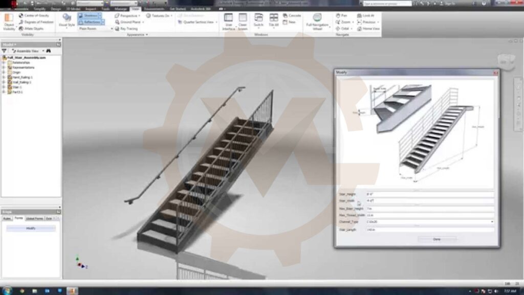
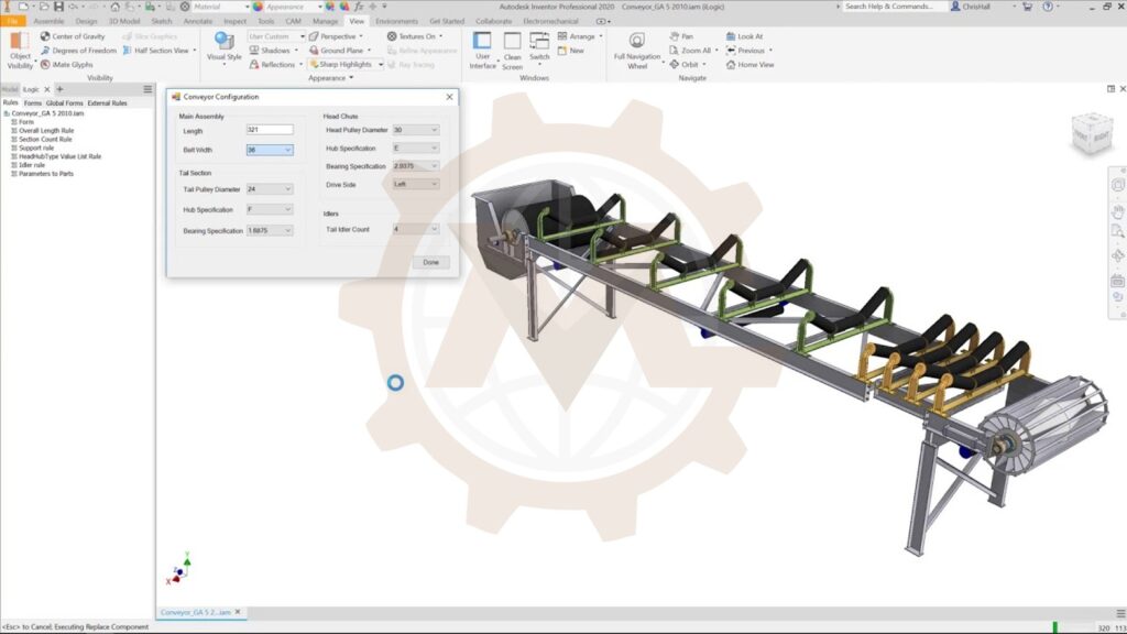
We develop Inventor product configurators that allow users to select equipment dimensions and options through a structured interface. Inputs may include height, width, length, capacity class, module count, access openings and equipment variants.
The configuration workflow can update the assembly and prepare agreed engineering outputs. Allowed ranges, discrete size options and incompatible combinations are defined with your team before implementation.
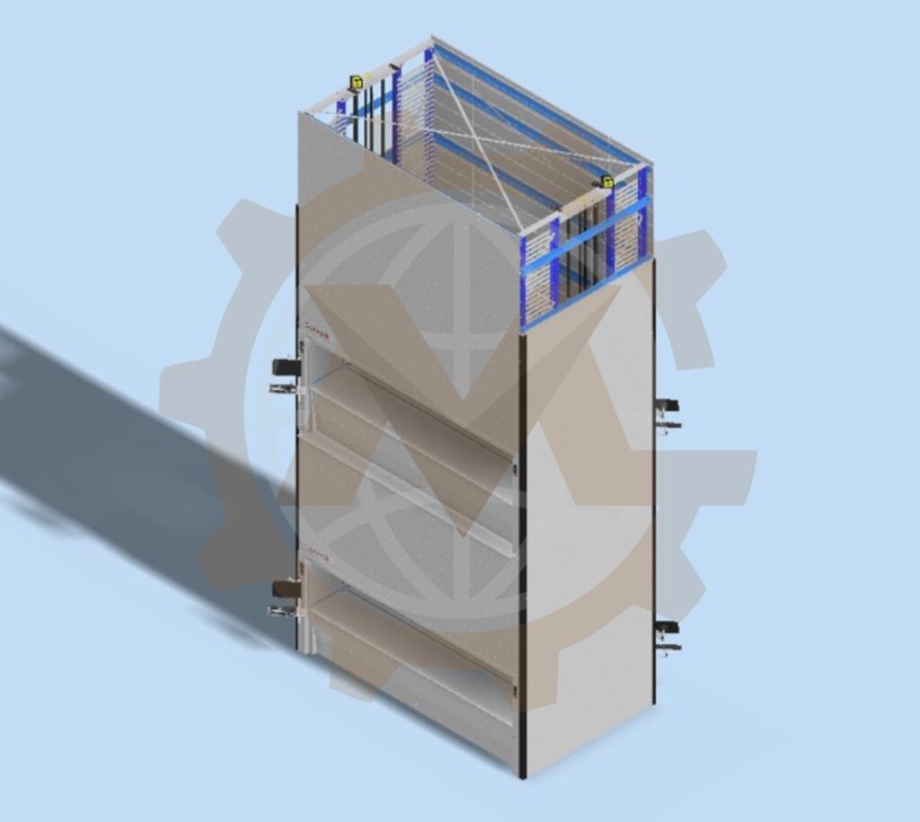
For example, a storage-machine configurator may control frame height, machine width, tray depth, opening locations and module quantities. These selections can drive the arrangement of the assembly and the information required for drawings and procurement.
Product Configurator Development
Inventor iLogic Forms and User Interfaces
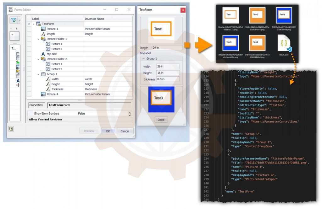
We create iLogic forms that organize product selections into a practical workflow. Depending on the chosen interface and Inventor version, the solution may include parameter fields, dropdown selections, option controls, grouped inputs and buttons for configuration or export tasks.
The interface should make the engineering choices easy to understand. We use clear units, meaningful labels and validation messages so users know which inputs are permitted and why a configuration may need revision.
Inventor iLogic Forms and User Interfaces
Parametric Model and Dimension Automation
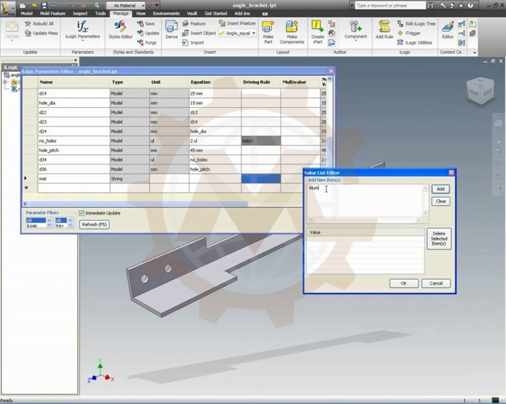
We connect iLogic rules with part and assembly parameters to automate repeatable geometry changes. Typical applications include adjusting frame dimensions, updating plate sizes, changing pattern quantities and coordinating dependent dimensions across several components.
Existing models are reviewed before automation begins. Where required, we restructure references, parameters and constraints to improve stability across the agreed configuration range. Automation cannot reliably compensate for an unstable underlying CAD model.
Parametric Model and Dimension Automation
Inventor iLogic Assembly Configuration
Assembly automation manages which components are required and how they are arranged for each product variant. The scope may include component activation or suppression, approved replacements, repeated modules, occurrence quantities and configuration-dependent positioning.
For large assemblies, the update sequence matters. We can organize configuration into stages—for example, frame, internal modules, mechanisms and covers—to manage dependencies and make the process easier to troubleshoot.
Inventor iLogic Assembly Configuration
Custom iLogic Rules and Programming
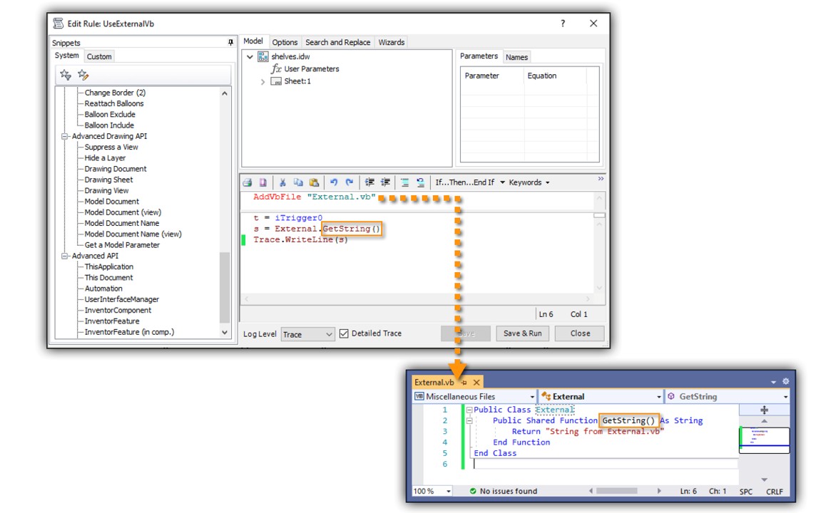
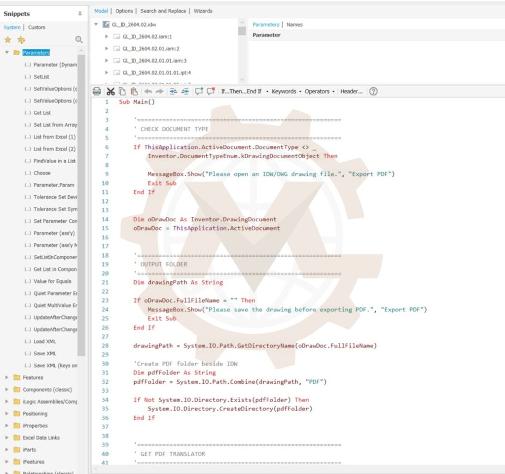
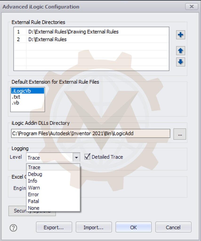
We develop internal and external iLogic rules for defined engineering tasks. Rules may cover parameter calculations, input validation, component selection, property updates, drawing operations and export workflows.
Code is organized around identifiable responsibilities and documented assumptions. Where useful, reusable routines handle common tasks such as locating documents, checking paths and preparing output names. This makes the delivered solution easier to understand and maintain.
Custom iLogic Rules and Programming
BOM and iProperties Automation
We automate agreed engineering data workflows using Inventor BOM information and document properties. Depending on your standards, this may include Part Number, Description, Title, material, project data and selected custom properties.
BOM export scope can include column selection, formatting, component filters and structured or parts-only views. Quantity handling, purchased items, reference components and merged part numbers are reviewed against your assembly’s BOM settings.
We distinguish document-level properties from occurrence-specific information. If a component is reused in several contexts, the chosen data storage method must avoid conflicting values.
Drawing Automation
Drawing workflows may include updating existing views, populating title blocks, applying agreed property values and generating documentation from prepared templates.
The scope is established around your drawing standards and product variation. Automatic dimension placement, sheet layouts and annotations may require additional development and review where geometry changes significantly. We define which drawing tasks are automated and which remain part of engineering approval.
PDF, DXF and STEP Export Automation
We develop export tools for selected documents, drawing sheets, assemblies or components. The workflow can prepare output folders, apply file naming rules and generate an agreed export summary.
Examples include separate PDFs for drawing sheets, STEP files for configured assemblies and DXF files for fabrication. Sheet-metal flat-pattern DXF and drawing-sheet DXF are different outputs; we define the intended use before building the export rule.
File selection, overwrite behavior, revision naming and excluded items are agreed during development so the output package fits your manufacturing workflow.
Design Copy and Save-As Workflows
For repeat orders, a configured design may need its own files and identifiers. We develop agreed design-copy or save-as workflows that manage output locations, naming conventions and assembly references.
The solution distinguishes shared library components from project-specific parts. This helps protect the master design and avoids unintentionally modifying common components when a new variant is created.
Existing iLogic Troubleshooting and Optimization
We review and improve existing Inventor iLogic code, forms and automation workflows. Typical issues include broken references, repeated rule execution, unreliable update sequences, inconsistent properties and failed exports.
The review starts with a reproducible example and the intended behavior. We identify the cause, revise the relevant logic and verify the affected workflow against agreed examples. Larger feature additions can be developed in stages after the existing system is stabilized.
Existing iLogic Troubleshooting and Optimization
Engineering Rules That Keep Configurations Under Control
A useful configurator needs more than editable dimensions. It must express the relationships that make a product variant acceptable.
Depending on the equipment, validation rules may check:
Minimum and maximum dimensions and permitted increments.
Compatibility between modules, openings and selected options.
Required clearances and allowable component arrangements.
Quantity limits and capacity-related selection conditions.
Required engineering properties before export.
Availability of templates, referenced files and output locations.
For example, an opening position may need to remain within the frame’s permitted region, or a tray selection may need to preserve a specified clearance. These conditions are incorporated from approved engineering requirements.
Configuration rules support design consistency. Load-bearing performance, fatigue, machinery safety and manufacturing quality still require the appropriate engineering verification for the product and its intended use.
Typical Equipment We Can Configure
Conveyor and Material Handling Equipment
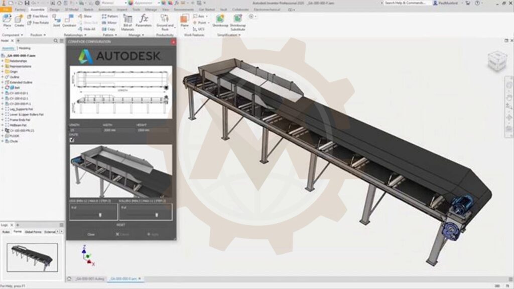
Configure conveyor lengths, widths, support arrangements and agreed module options. Automation can coordinate repeatable components and documentation across a defined conveyor family. Explore Conveyor Design Services
Conveyor and Material Handling Equipment
Lifting and Vertical Storage Systems
Develop configuration workflows for frame sizes, storage modules, trays, access openings and related equipment arrangements. Product rules are coordinated with the underlying mechanical design and its approved operating range. Explore Lifting System Design Services
For companies that already have stable CAD models, a smaller automation project can focus on property standardization, BOM export, drawing updates or manufacturing file preparation. A full product configurator is not required to improve a repeatable documentation task.
From Manual Revisions to a Controlled Configuration Workflow
Consider a machine family where engineers manually edit frame dimensions, add modules, adjust covers and prepare a BOM for every order.
An agreed iLogic workflow could follow this sequence:
Enter the required machine dimensions and select product options.
Check the inputs against approved configuration rules.
Update the frame and dependent components.
Configure modules, mechanisms and covers in the defined sequence.
Update engineering properties and prepare the selected BOM view.
Update the agreed drawing package.
Generate the requested manufacturing exports.
Review the configuration and outputs before release.
The exact sequence depends on the assembly structure and documentation requirements. The aim is to reduce repetitive editing while keeping engineering review visible.
Our iLogic Development Process
1. Review the Product and Existing Inventor Files
We review your master assembly, representative variants, drawings, templates and current workflow. We identify which tasks are repeatable and which decisions require engineering judgment.
2. Define Configuration Logic and Acceptance Criteria
Together, we establish input ranges, allowed options, dependencies, naming rules and expected outputs. The proposal identifies supported Inventor versions, included features, exclusions and representative acceptance cases.
3. Prepare the CAD Model for Automation
Where required, we improve parameter naming, assembly structure, component references and reusable templates. The goal is a model that behaves predictably within the agreed range.
4. Develop Rules, Forms and Output Workflows
We implement the agreed logic and interface, then connect configuration to properties, BOMs, drawings and exports. Larger projects can be divided into functional milestones so your team can review each stage.
5. Test Configurations and Review Results
Testing covers representative variants, boundary dimensions, incompatible selections and the agreed output workflows. We check model updates, required clearances, component quantities and file generation for the selected cases. The possible combination count is different from the number of tested configurations. We document the acceptance sample and any known limitations rather than implying that every possible variant has been individually verified.
6. Deliver and Support the Agreed Workflow
We provide the automation package, setup guidance and agreed operating instructions. Post-delivery support, bug-fix periods and future feature development are defined in the project scope.
Project Deliverables
The delivery package is tailored to the project. It may include:
Deliverable
Typical contents
Configurable Inventor files
Approved master parts and assemblies with the agreed parameter structure
iLogic development files
Internal or external rules and supporting code covered by the agreement
Configuration interface
Forms, input controls and workflow buttons
Engineering output tools
Agreed BOM, drawing and export routines
Templates and settings
Required drawing templates, property mappings and naming conventions
Setup documentation
Folder structure, dependencies, software version and installation steps
User guidance
Configuration steps, output procedures and troubleshooting notes
Acceptance record
Tested cases, expected outputs and known limitations
Source-code ownership, third-party dependencies and permitted reuse are clarified in the commercial agreement. Native Inventor files and neutral output formats are supplied according to the agreed scope.
Automating predictable edits allows engineers to spend more time on exceptions, product development and technical review.
More Consistent Product Variants
Shared configuration rules help teams apply the same dimensions, component choices and naming standards across repeat orders.
Better Coordination Between Models and Outputs
A defined workflow helps connect the configured assembly with the properties, BOM and documentation that manufacturing receives.
A Maintainable Platform for Future Development
Organized rules and documented dependencies make it easier to add agreed product options and extend workflows as the product family develops.
The benefits depend on model complexity, update performance and the amount of repeatable work. Where measurable targets are needed, we can agree baseline tasks and compare completion time and output quality during acceptance.
Why Work with GMD for Inventor iLogic Development?
Mechanical Design Understanding
GMD combines mechanical design experience with Inventor workflow development. Configuration logic is considered alongside assembly behavior, fabrication requirements and engineering documentation.
Autodesk Inventor as a Core Engineering Platform
Our services include Inventor modeling, assemblies, drawings and BOM preparation. This allows automation development to connect with the wider CAD workflow rather than stop at individual scripts.
Defined Scope and Reviewable Milestones
We establish requirements, outputs and acceptance examples before development. Your team can review the intended behavior and confirm progress through agreed milestones.
Remote Collaboration and Confidentiality
We support remote engineering collaboration for international clients. Confidential models, product rules and client information are handled under the agreed confidentiality and access arrangements.
Please share the information available for your project:
Inventor version and representative part or assembly files.
Existing iLogic rules or forms, if applicable.
Product dimensions, options and configuration restrictions.
A description or video of the current manual workflow.
Example BOMs, drawings and required exports.
File naming, folder and revision requirements.
Expected users, deployment arrangement and project timeline.
Acceptance examples and any target workflow improvements.
If the product rules are not yet documented, we can begin with a requirements review to define an achievable first stage.
Frequently Asked Questions About Inventor iLogic Services
What is the difference between parametric modeling and iLogic automation?
Parametric modeling establishes dimensions and relationships within the CAD model. iLogic adds rules that coordinate inputs, select options and execute tasks across the workflow. A reliable configurator generally needs a well-structured parametric model underneath its rules.
Can you add iLogic to an existing Inventor assembly?
Yes. We first review the assembly’s parameters, references, constraints and intended variants. Some models can be automated directly; others require restructuring before configuration rules can operate reliably.
Can you create custom Inventor iLogic forms?
Yes. We develop forms for agreed dimensions, options and workflow actions. More advanced interface requirements are reviewed separately to select a suitable implementation.
Can Inventor iLogic run rules automatically?
Rules can be associated with supported document events through event triggers. We select triggers carefully to avoid unnecessary updates, repeated execution or exports occurring at the wrong stage of the workflow.
Can you automate BOMs and manufacturing file exports?
Yes. The scope can include BOM export and PDF, DXF or STEP generation. We agree document selection, naming rules, export settings and destination folders before development.
Can iLogic generate drawings automatically?
Drawing tasks can be automated using suitable models and templates. The achievable scope depends on variation in geometry, dimensioning and sheet layout. We define the automated tasks and required review steps for your project.
Do you use the Inventor API as well as iLogic?
Where required, iLogic development can use the Inventor API for more detailed document and object operations. The implementation depends on the workflow, software version and maintenance requirements.
Can you fix or improve existing iLogic code?
Yes. We review the current rules and reproduce the reported issue. The revised workflow is checked against agreed cases before delivery.
How many configurations can an Inventor configurator support?
The number depends on the dimensions and options permitted by the product rules. A large theoretical combination count does not establish that every variant is mechanically valid or tested. We define permitted combinations and a practical verification plan for the agreed product range.
Will the solution work in every Inventor version?
Compatibility is defined for the agreed version or versions. API behavior, document features and file compatibility can differ, so deployment and testing are planned for the client’s actual environment.
Can you provide an iLogic tutorial or user handover?
Project-specific instructions or a handover session can be included so your team understands how to operate the delivered tool. General training courses and ongoing development support are separate scopes unless agreed.
How is an iLogic automation project priced?
Pricing depends on CAD model readiness, configuration complexity, interface requirements, outputs and testing scope. We review representative files and requirements before preparing a proposal. Larger projects can be divided into stages with defined deliverables.
Build a More Efficient Inventor Configuration Workflow
Have a repeatable machine design or an Inventor task your team performs for every order? Share your assembly, configuration requirements or current workflow with GMD. We will help define a practical iLogic development scope—from a focused automation rule to a configurable machine family with agreed engineering outputs.
We use cookies to make our website work, analyse traffic and improve your experience. You can accept all cookies, deny non-essential cookies or manage your preferences. You can change your choice at any time. For more information, please see our Cookie Policy.
Functional
Always active
The technical storage or access is strictly necessary for the legitimate purpose of enabling the use of a specific service explicitly requested by the subscriber or user, or for the sole purpose of carrying out the transmission of a communication over an electronic communications network.
Preferences
The technical storage or access is necessary for the legitimate purpose of storing preferences that are not requested by the subscriber or user.
Statistics
The technical storage or access that is used exclusively for statistical purposes.The technical storage or access that is used exclusively for anonymous statistical purposes. Without a subpoena, voluntary compliance on the part of your Internet Service Provider, or additional records from a third party, information stored or retrieved for this purpose alone cannot usually be used to identify you.
Marketing
The technical storage or access is required to create user profiles to send advertising, or to track the user on a website or across several websites for similar marketing purposes.