Lifting System Design Services / Hydraulic Lifting Design
Custom Hydraulic Lifting System Design Services
Custom Hydraulic Lifting Systems Engineered Around Your Machine and Workflow.
GMD designs integrated hydraulic lifting systems for industrial equipment, production lines and material handling. We develop the mechanism, structure, hydraulic architecture and manufacturing documentation around your load, travel, cycle time and site constraints.
An industrial lifting system must do more than raise a specified weight. It must position the load where the process needs it, complete each cycle at the required pace, fit within the available space and remain serviceable throughout its operating life.
GMD provides custom hydraulic lifting system design services for machine builders, manufacturers and system integrators. We develop lifting concepts and detailed engineering packages for equipment that moves, positions, tilts or transfers industrial loads. Our work can connect mechanical design, hydraulic component selection, controls interfaces and manufacturing documentation within one coordinated design.
Whether your project begins with a specification, an early CAD concept or an existing machine that needs improvement, we can define the lifting arrangement and develop the agreed design deliverables.
What Is a Custom Hydraulic Lifting System?
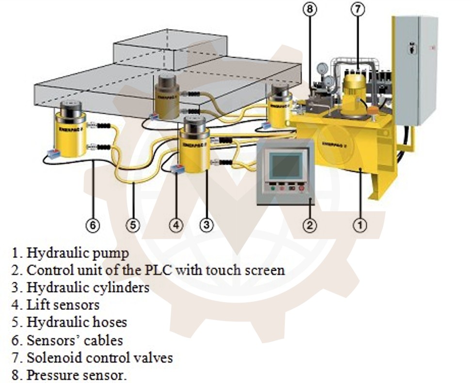
A hydraulic lifting system uses pressurized fluid to produce controlled force and movement. In an industrial machine, the complete system may include cylinders, a guided platform or lifting mechanism, a hydraulic power unit, valves, piping or hoses, sensors, structural supports and controls.
“Custom” means these parts are selected and arranged for a defined lifting task. The design must account for the actual load path, mounting conditions, travel, operating sequence, surrounding equipment and foreseeable off-center loading. A cylinder with enough theoretical force does not, by itself, establish that the machine can lift safely or perform the required cycle.
Hydraulic systems can suit applications that need high force within a constrained space, controlled movement or integration with another mechanical operation. Their suitability must still be assessed against alternatives such as electric screw drives, belt or chain lifts, and other lifting mechanisms.
Hydraulic Lifting Systems We Can Design
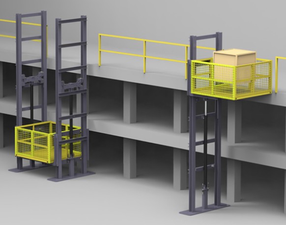
Industrial lifting platforms
We design guided platforms that move products, fixtures or equipment between defined working heights. The arrangement may include one or more cylinders, guide rails, rollers, mechanical stops, load restraints and transfer interfaces.
Industrial lifting platforms
Hydraulic material handling lifts
A material handling lift can connect production stages, storage positions or loading points. We assess how the load enters and leaves the platform, including transfer forces, conveyor interfaces, landing alignment and controls handshakes.
Hydraulic material handling lifts
Hydraulic lift tables
Lift tables position a load at a useful working height. Depending on the task, the design may use a direct-acting, guided or scissor mechanism. We consider platform size, collapsed height, travel, load distribution and access around the table.
Hydraulic lift tables
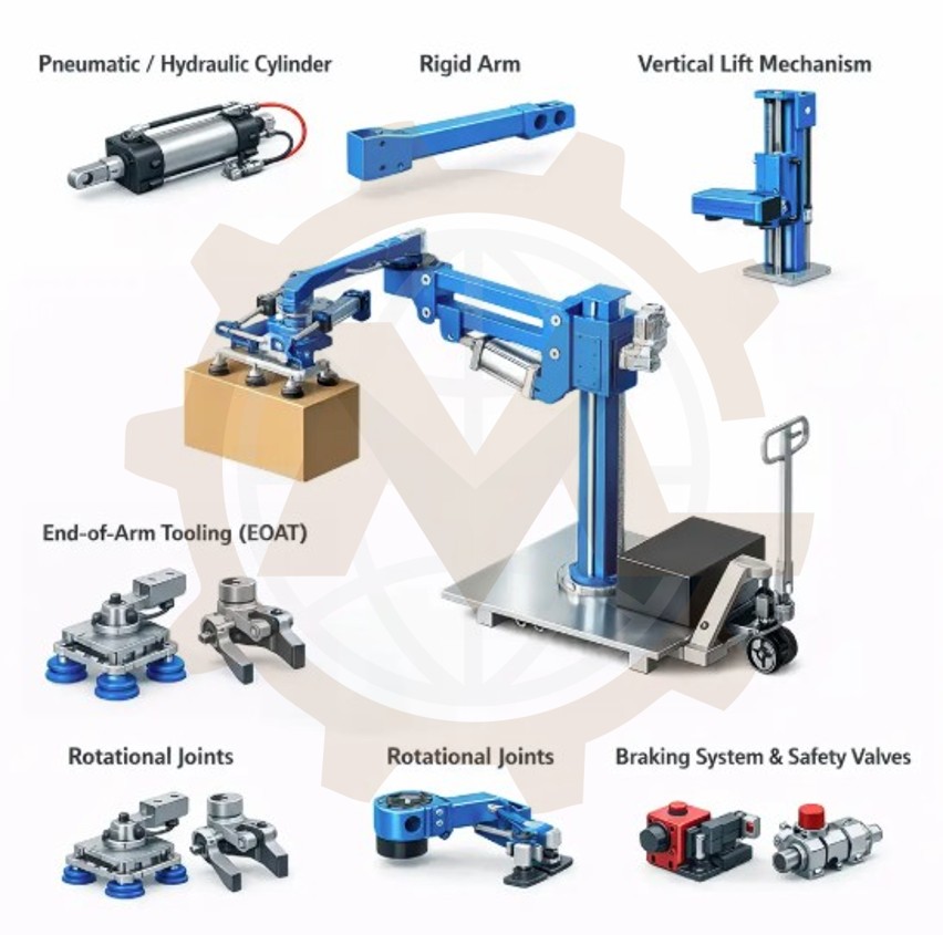
Machine-integrated lifting mechanisms
A lift may be one motion within a larger machine. Examples include raising a process fixture, positioning a tooling assembly or moving a product into a loading station. Here, the lifting sequence must be coordinated with guards, sensors and adjacent mechanisms.
Machine-integrated lifting mechanisms
Multi-cylinder lifting systems
Large platforms or uneven loads may call for more than one actuator. We evaluate cylinder placement, structural load sharing, guidance and the method used to control position differences between sides.
Multi-cylinder lifting systems
Retrofit and redesign projects
We can review an existing lift when it has limited capacity, excessive deflection, unreliable positioning, difficult maintenance or a change in operating requirements. The starting point is an assessment of available drawings, component data, measured geometry and the machine’s operating history.
Engineering Starts With the Complete Lifting Duty
A rated payload is only one design input. Before selecting a mechanism, we define the motion and the loads acting throughout it:
Maximum and minimum product mass.
Load dimensions, support points and center of gravity.
Foreseeable off-center or uneven loading.
Platform, fixture and moving-component mass.
Required travel, lower height and upper height.
Lifting and lowering speeds.
Acceleration, deceleration and stopping requirements.
Cycles per hour, shift pattern and expected duty.
Loading method and forces from connected equipment.
Power supply, available installation space and mounting conditions.
The most demanding condition may occur during starting, stopping, transfer or an offset-load case rather than while holding a centered load at rest. We use the agreed design cases to develop and check the system.
Choosing the Right Lifting Mechanism
Hydraulic actuation can be applied through different mechanical arrangements. The choice affects cylinder force, required stroke, side loading, platform guidance, maintenance and the overall machine envelope.
Arrangement
Where it may fit
Main design questions
Direct-acting cylinder
A guided platform with a suitable cylinder installation space
Cylinder stroke, alignment, buckling and load guidance
Scissor mechanism
A compact lowered height with greater platform travel
Force variation through the stroke, pivots, stability and guidance
Reeved lift
Greater platform travel than direct cylinder stroke
Chain or cable forces, equalization, wear and load retention
Multiple cylinders
A broad platform or distributed lifting points
Load sharing, synchronization and response to unequal loading
Hydraulic motion within a machine
A lift integrated into another process
Clearances, controls sequence and interactions with nearby mechanisms
We compare arrangements against the project requirements before committing to detailed CAD. A mechanism that fits the available space must also provide a practical path for fabrication, adjustment, inspection and repair.
Cylinder sizing begins with the forces produced by the actual mechanism. For a direct-acting arrangement, fluid pressure and effective piston area establish an initial force estimate. Linkages and scissor mechanisms require force to be checked across the full travel because their mechanical advantage changes with position. Manufacturer sizing tools also relate effective area, pressure, flow and cylinder speed.
We then review bore, rod diameter, stroke, mounting style, buckling risk, alignment, side-load exposure and end-of-stroke behavior. Pressure losses, friction and appropriate design allowances are considered with the selected hydraulic circuit.
Cylinder force and geometry
Pump, motor and power unit
The power unit must supply the flow and pressure required by the operating sequence. We assess pump delivery, motor power, reservoir arrangement, filtration, temperature behavior and maintenance access. A machine with frequent cycles may impose a very different thermal duty from one that lifts the same load occasionally.
Pump, motor and power unit
Valves and motion control
The hydraulic circuit must define how the load raises, holds and lowers. Depending on the architecture, it may require pressure control, directional control, flow control, load holding, controlled lowering and provisions for fault recovery. The selection and placement of these functions depend on the specific machine and its risk assessment.
Valves and motion control
Hoses, tubes and connections
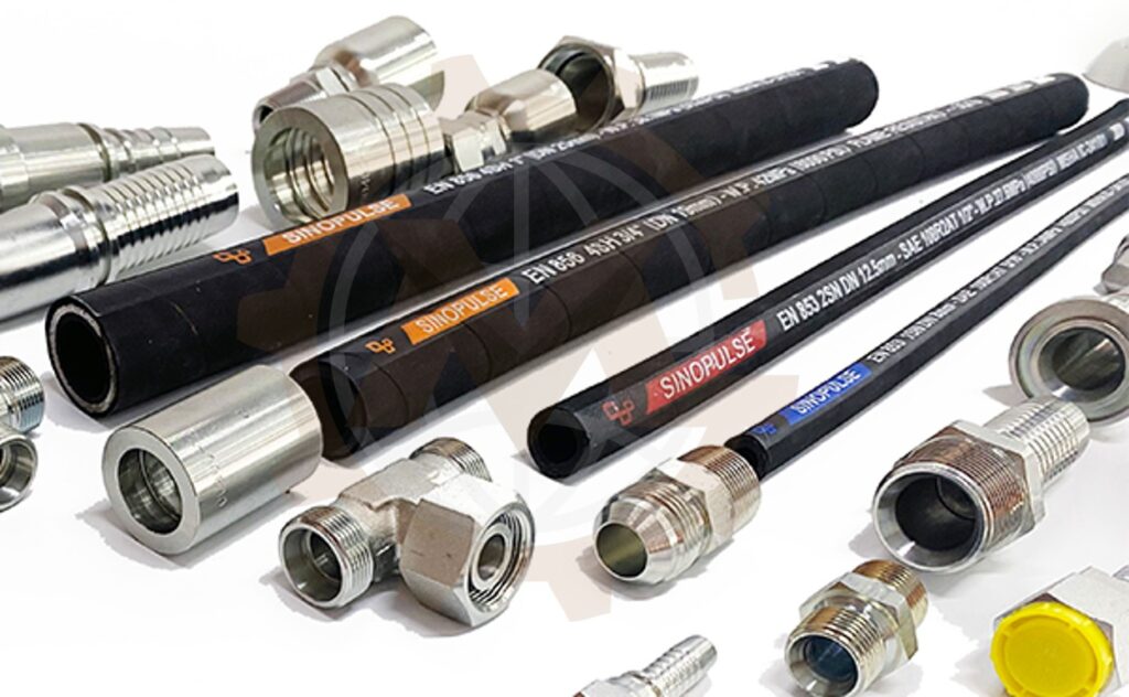
Hydraulic routing affects reliability and service work. We account for pressure rating, movement, bend radius, abrasion, supports, access to fittings and protection from nearby mechanisms. Routing should be developed in the 3D assembly before the machine becomes difficult to change.
Hoses, tubes and connections
Structural Design and Load Path
The hydraulic components generate force, but the structure must carry it into the floor or supporting machine. GMD develops the load path through the platform, guides, cylinder mounts, frame and installation interfaces.
The structural assessment can include:
Platform bending and local loads at product contact points.
Frame stiffness and alignment over the travel.
Cylinder mounting and pin reactions.
Guide and roller reactions under offset loads.
Shaft, pivot, bearing and connection loads.
Anchorage and support reactions supplied to the responsible facility team.
Clearances when components deflect under load.
Fatigue considerations where repeated cycling makes them relevant.
FEA can support the design of critical parts or frames when appropriate. It is used alongside defined load cases, connection details and engineering judgment.
Structural Design and Load Path
Speed, Positioning and Cycle Time
Specifying a lifting speed alone does not establish machine throughput. An operating cycle can include loading, load detection, guard closure, lift movement, settling, positioning, unloading and return travel.
We map the complete sequence and identify where time is spent. Flow rate influences cylinder speed, while acceleration, valve behavior, structural movement and the connected process affect the time required to reach a usable position. The required positioning accuracy should be defined at the interface where the product transfers or the process operates.
For multi-cylinder systems, leveling and synchronization must also be addressed. The appropriate method depends on load variation, accuracy requirements, hydraulic architecture and controls strategy.
Safety, Load Holding and Maintenance Access
Hydraulic lifting equipment can expose people to raised loads, moving platforms, pinch points, stored pressure and unexpected motion. Safety measures must follow the intended use and a risk assessment for the complete machine.
Design considerations may include guarding, interlocked access, overtravel detection, overload monitoring, controlled stopping, load-holding arrangements and a defined response to power loss or hydraulic faults. Maintenance beneath a raised structure requires a suitable method of securing it and controlling hazardous energy; the hydraulic circuit alone should not be assumed to provide a safe maintenance support. OSHA’s hazardous-energy rule addresses isolation and securing or blocking equipment during servicing.
For hydraulic system design, ISO 4413 sets general rules and safety requirements for hydraulic fluid power systems used on machinery. The complete set of applicable standards depends on the machine category, intended use and installation jurisdiction.
Controls and Production-Line Integration
A custom lift often works as part of a larger system. Its mechanical design needs clear interfaces with the electrical and controls design, including:
Upper, lower and intermediate position detection.
Load-present and product-clear signals.
Guard, gate and access-door states.
Hydraulic pressure, temperature and filter monitoring where specified.
Permissive signals to connected conveyors or machines.
Manual, automatic, setup and maintenance modes.
Defined responses to interrupted transfers and sensor faults.
GMD can coordinate these interfaces with the client’s controls team. Electrical design or PLC programming can be included when agreed in the project scope.
Oil cleanliness, component access and environmental protection influence long-term performance. We consider filtration, filling and draining, hose replacement routes, cylinder access, leak containment and suitable protection against site conditions.
The design brief should identify dust, washdown, moisture, temperature, corrosive exposure or cleanliness requirements early. Those conditions can change material, seal, hose, coating and enclosure choices.
GMD’s Design Process
1. Review requirements and existing information
We collect drawings, product data, load cases, site constraints, target cycle time and required interfaces. Missing inputs are recorded as assumptions for review.
2. Develop the system concept
We establish the mechanism, hydraulic architecture, overall envelope and main load paths. Where useful, we compare concepts against height, stroke, speed, manufacturing complexity and access requirements.
3. Complete calculations and component selection
We assess the relevant forces, cylinders, pump flow, motor power, structure, guides and key purchased components. The calculations are matched to the agreed operating and fault cases.
4. Build the coordinated 3D design
Using Autodesk Inventor, we model the mechanism, structure, hydraulic-component locations and interfaces. Motion and clearance reviews help identify conflicts before drawing release.
5. Prepare manufacturing documentation
The agreed package may include assembly models, fabrication drawings, machined-part drawings, hydraulic schematics or interface information, a BOM and STEP files.
6. Review and revise
We coordinate comments from the client, fabricator, component suppliers and controls team. Revisions are incorporated into the deliverables according to the agreed project scope.
Typical Design Deliverables
A project may include:
Design basis and agreed operating assumptions.
Concept layouts and general arrangement drawings.
Mechanism and hydraulic sizing calculations.
3D parts and assemblies.
Cylinder, power-unit and component specifications.
Hydraulic circuit and controls interface information, where included.
Fabrication, machining and assembly drawings.
Bill of materials.
STEP and PDF exchange files.
Revision updates and technical coordination.
The proposal will state exactly which documents and engineering disciplines are included.
Why Work With GMD?
GMD combines mechanical machine design with hydraulic-system thinking. We consider the lift as part of the production process: how the load arrives, where it must stop, how it leaves and how the equipment will be built and maintained.
Our team has more than 10 years of mechanical design experience and works primarily in Autodesk Inventor. We support manufacturers and integrators remotely across international projects, producing coordinated 3D models, manufacturing drawings and BOMs. Project confidentiality and IP requirements can be addressed in the service agreement.
Information to Send for a Design Quotation
To help us define the work, please share:
Description and drawings of the load.
Maximum mass and expected center-of-gravity range.
Required platform or fixture dimensions.
Lower and upper positions, stroke and available machine space.
Target speed, cycle time and daily operating pattern.
Loading, unloading and connected-equipment details.
Existing CAD models, sketches or reference photos.
Available electrical power and preferred hydraulic components.
Installation location, environment and target market.
Required deliverables and project schedule.
We can begin with a concept study when some parameters are still being determined.
Frequently Asked Questions
Can GMD design both the lifting mechanism and hydraulic circuit?
Yes, these can be developed as one coordinated engineering scope. The proposal will define the mechanical, hydraulic and controls deliverables and the responsibilities of each project party.
How do you choose between a direct-acting lift and a hydraulic scissor lift?
We compare required travel, collapsed height, available cylinder space, force over the stroke, platform stability and maintenance access. The load and layout determine which concept should proceed to detailed design.
Can a hydraulic lifting system be integrated with a conveyor?
Yes. The design must include the conveyor’s own weight, product load, transfer forces, stopping position, cable or hose routing and the operating sequence with adjacent equipment.
Can you design a system with two or more cylinders?
Yes. The design must address load sharing, platform guidance, synchronization, unequal loading and the response if one side moves differently from another.
What happens if electrical power is lost?
The required behavior must be defined for the particular machine. We evaluate how the load is held, how movement stops and what recovery or lowering method is appropriate for the application.
Can GMD improve an existing hydraulic lift?
Yes. An assessment can target insufficient capacity, inconsistent motion, excessive deflection, component access or changed product requirements. Existing documentation and machine measurements help establish a reliable starting point.
Do you manufacture or install the finished equipment?
This page describes engineering design services. Manufacturing, installation, commissioning and final certification should be included only where specifically agreed with the responsible parties.
Start Your Hydraulic Lifting System Project
Tell us what the load must do, where it must move and how the lift fits into your process.GMD can turn those requirements into a defined lifting concept and a practical engineering package for the next stage of your project.
We use cookies to make our website work, analyse traffic and improve your experience. You can accept all cookies, deny non-essential cookies or manage your preferences. You can change your choice at any time. For more information, please see our Cookie Policy.
Functional
Always active
The technical storage or access is strictly necessary for the legitimate purpose of enabling the use of a specific service explicitly requested by the subscriber or user, or for the sole purpose of carrying out the transmission of a communication over an electronic communications network.
Preferences
The technical storage or access is necessary for the legitimate purpose of storing preferences that are not requested by the subscriber or user.
Statistics
The technical storage or access that is used exclusively for statistical purposes.The technical storage or access that is used exclusively for anonymous statistical purposes. Without a subpoena, voluntary compliance on the part of your Internet Service Provider, or additional records from a third party, information stored or retrieved for this purpose alone cannot usually be used to identify you.
Marketing
The technical storage or access is required to create user profiles to send advertising, or to track the user on a website or across several websites for similar marketing purposes.