Lifting System Design Services / vertical lift module design
Vertical lift module design services
Custom Vertical Lift Module Design for Smarter Industrial Storage
GMD designs automated tray storage systems around your products, available space, load requirements and retrieval workflow. From lift mechanisms and structural calculations to 3D CAD, manufacturing drawings and BOMs, we help turn your VLM concept into a buildable machine.
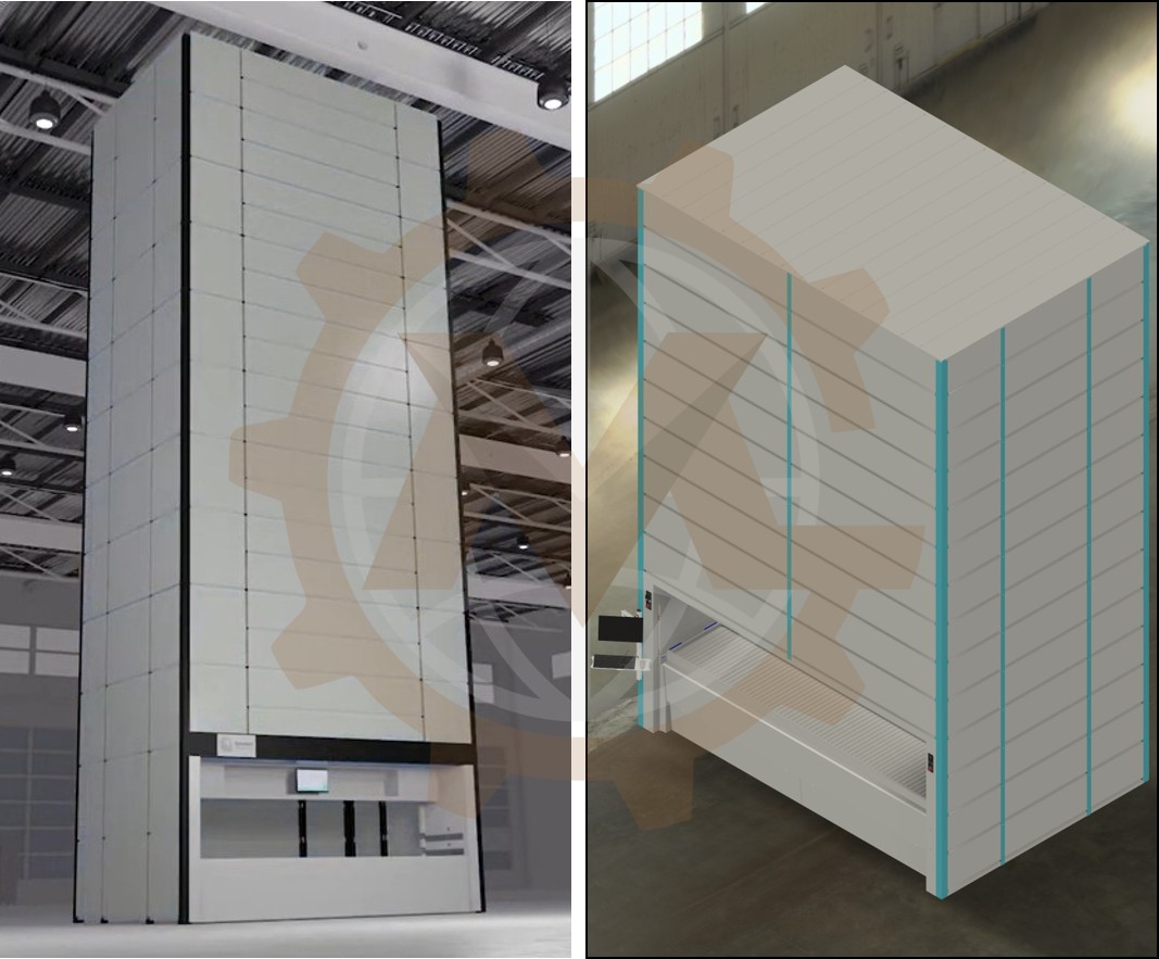
A vertical lift module can store a large number of trays within a compact floor area and bring the requested tray to an accessible opening. For manufacturers and system integrators, however, an effective VLM requires more than a tall enclosure and a moving platform. Tray dimensions, payload variation, extraction geometry, drive duty, structural stiffness, access openings, controls interfaces and maintenance access must work together.
GMD provides vertical lift module design services for companies developing a new automated storage machine or improving an existing design. Our mechanical engineering work can cover concept development, mechanism selection, engineering calculations, Autodesk Inventor 3D models, production drawings and bills of materials. We can also coordinate mechanical interfaces with your electrical, controls, fabrication and installation teams.
What Is a Vertical Lift Module?
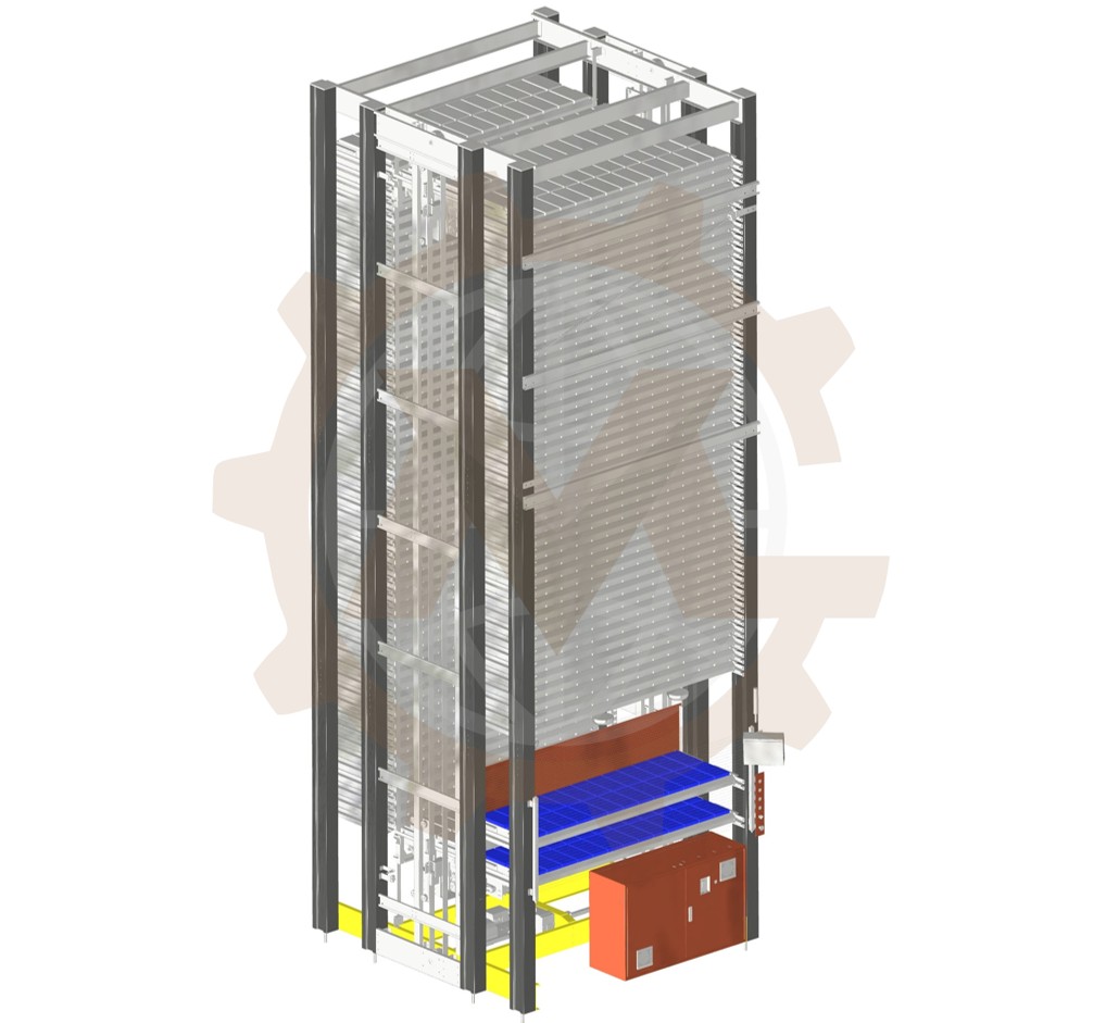
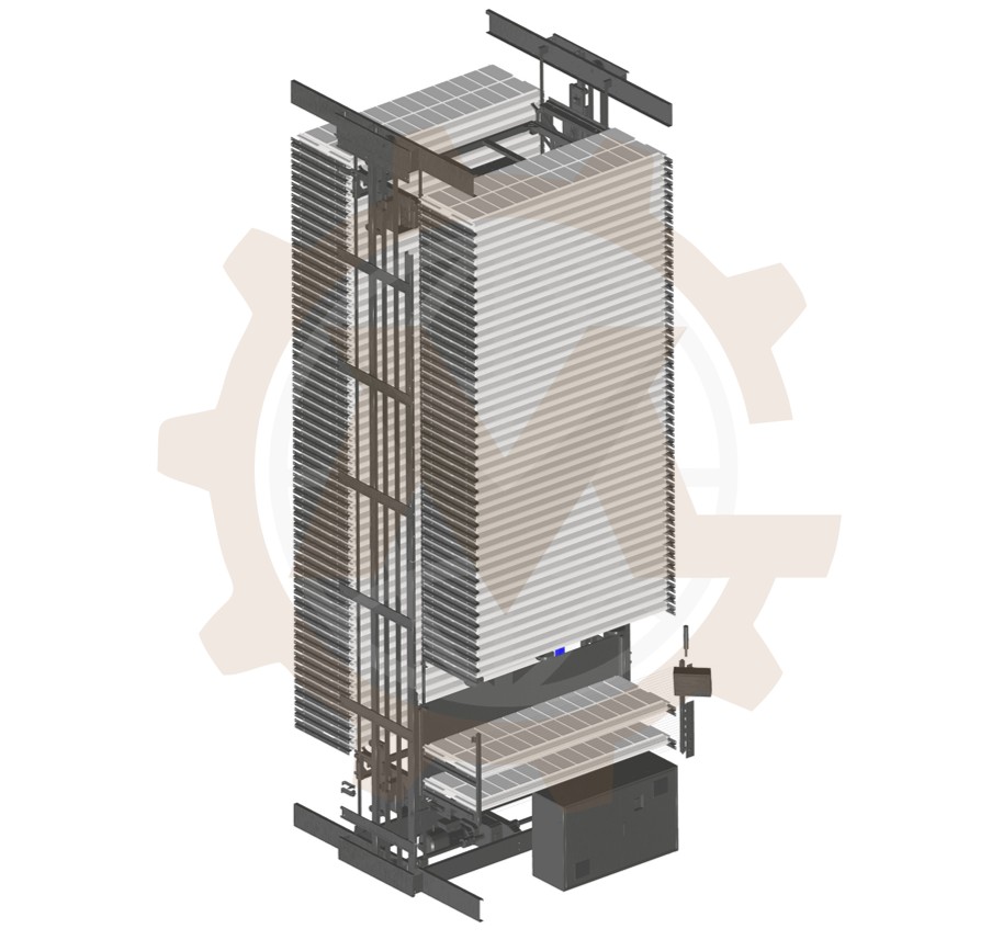
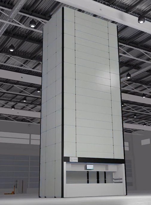
A vertical lift module, or VLM, is an automated storage and retrieval system that holds items on trays inside a vertical structure. In a common arrangement, trays are stored in columns on either side of a central lifting mechanism. An extractor retrieves the selected tray, brings it to an access opening and returns it to an available storage position after the operator or connected equipment finishes its task.
Some VLM systems measure the height of stored items and use that information to allocate tray positions more efficiently. The exact layout, tray handling method and storage logic vary by machine design.
VLMs are used for spare parts, tools, components, kits and other inventory that benefits from organized, controlled access. They can operate as stand-alone storage equipment or connect to broader inventory and warehouse workflows.
Custom VLM Design Around Your Storage Requirements
A custom VLM should begin with the inventory and the way people or machines will retrieve it. GMD develops the mechanical arrangement around inputs such as:
Stored products: dimensions, mass, packaging, fragility, center of gravity and expected changes in product mix.
These requirements guide the architecture. A machine optimized only for maximum theoretical tray count may be difficult to load, service or operate at the required pace. We evaluate usable capacity and day-to-day operation together.
Our Vertical Lift Module Engineering Scope
VLM concept and layout development
We develop an overall machine layout that establishes the storage columns, lifting path, tray transfer method, access openings, frame, service zones and facility interfaces. Where appropriate, we compare concepts for their footprint, mechanical complexity, capacity, accessibility and manufacturing requirements.
VLM concept and layout development
Tray and storage position design
We design trays and their supporting interfaces for the specified payload and product arrangement. The work may include tray stiffness, support rails, extraction contact points, retention details, adjustable positions and practical clearances for loading and retrieval.
Tray payload and dimensions must be evaluated together. A wide tray carrying an unevenly distributed load can create a different structural and drive case from a centrally loaded tray of the same total mass.
Tray and storage position design
Lift and extractor mechanism design
The lift and extractor must locate a tray, support it during transfer and move it without unwanted interference. Depending on the chosen concept, our work may cover guides, rollers, shafts, lifting elements, transfer arms, positioning features, adjustment provisions and the mechanical interfaces to sensors.
We check how tolerances, frame deflection and tray variation affect engagement throughout the machine height—not only at one nominal position.
Lift and extractor mechanism design
Frame and enclosure engineering
The frame must support stored trays and dynamic loads while maintaining alignment between storage positions and the moving mechanism. We develop the frame, covers, doors and mounting interfaces with attention to fabrication, assembly, transport and site installation.
Frame and enclosure engineering
Drive selection and mechanical calculations
Drive engineering can include motor and gearbox sizing, lifting forces, torque, power, acceleration, braking and duty. We assess the mass of the tray, payload and moving structure, along with friction, transmission efficiency and the required operating cycle.
Where the design calls for it, we also assess shafts, bearings, chains, belts, couplings, guides and connection details. Component selection is based on the defined operating cases and manufacturer data, then reviewed against the complete machine arrangement.
Drive selection and mechanical calculations
CAD, drawings and BOMs
GMD develops coordinated 3D CAD models, manufacturing drawings and bills of materials. Depending on project scope, deliverables may include general arrangements, fabrication drawings, machined-part drawings, assembly drawings, purchased-part lists and STEP files.
Autodesk Inventor is our primary CAD platform. We can also support configuration logic in iLogic when the project requires multiple machine heights, widths, tray depths or opening arrangements.
Design Considerations That Shape VLM Performance
Capacity and tray spacing
The number of trays that fit in a machine depends on more than enclosure height. Tray depth, product height, support geometry, extraction clearance and reserved maintenance space all affect usable capacity.
A height-measurement feature may allow a VLM to place trays according to their actual contents rather than one fixed storage pitch. Whether that feature is worthwhile depends on the inventory profile and the intended control architecture.
Retrieval time and throughput
A realistic cycle-time estimate includes request processing, lift motion, acceleration and deceleration, extraction, tray presentation, operator or automated handling, and return travel. Peak demand, frequently accessed items and the number of access openings can matter as much as maximum travel speed.
We use the expected operating sequence to assess whether the proposed configuration can support the required workflow. Claimed tray rates should always be tied to a defined sequence and load case.
Uneven and changing loads
Stored items are not always centered. We consider foreseeable offset loads, tray deflection, guide reactions and the effect of different payloads at different positions in the machine. These cases inform the tray structure, lifting mechanism, guides and frame.
Access and ergonomics
The opening position influences loading effort, picking access and the layout of nearby workstations. Multiple access openings or integration with conveyors and robots add further transfer and guarding requirements. Commercial VLM systems use a variety of access and automated handling arrangements, so the interface should be specified for the actual workflow.
Maintenance and recovery
Service access should be considered while the architecture is still flexible. We review access to drives, guides, sensors, lifting components and tray transfer points, along with practical ways to inspect, adjust and replace components. Recovery from a misplaced tray or interrupted cycle also needs a defined mechanical and controls concept.
Safety and system boundaries
Moving trays and extractors can create trapping, crushing and falling-load hazards. Guarding, access doors, interlocks, braking, overload detection and maintenance procedures must be developed for the intended use and installation location. The applicable requirements and final validation should be established for each project and agreed with the responsible machine builder and controls team.
Vertical Lift Module vs. Vertical Carousel
Both systems can bring stored goods to an access point, but their internal movement differs. A VLM generally selects and retrieves an individual tray using a central extractor. A vertical carousel moves its carriers around a continuous loop. That difference affects storage flexibility, mechanical layout and how a requested carrier reaches the operator.
Design question
Vertical lift module
Vertical carousel
How is an item retrieved?
A selected tray is extracted and delivered
Carriers circulate until the selected one reaches the opening
How are storage positions arranged?
Individual tray locations within a vertical structure
Carriers connected in a continuous loop
What should be evaluated?
Tray height variation, extraction geometry and lift cycle
Carrier pitch, loop movement and product fit
The right option depends on inventory dimensions, access frequency, required throughput, available space and the operating workflow. GMD can evaluate these inputs during concept development.
Applications for Custom Vertical Storage Systems
A VLM design may support:
Industrial spare parts and maintenance inventory.
Manufacturing components and work-in-process kits.
Tools, fixtures and changeover parts.
Warehouse picking and order fulfillment.
Automotive and equipment parts.
Electrical and electronic components, subject to their handling requirements.
Sheet metal parts or other specialized loads when tray design and handling equipment are developed for them.
The product category alone does not determine the machine specification. Two facilities storing similar parts may need different tray loads, access arrangements and retrieval rates.
Our VLM Design Process
1. Define the design brief
We collect product and tray data, capacity targets, site constraints, operating sequences and interfaces. We also identify the party responsible for controls, fabrication, installation and final machine validation.
2. Develop and review the concept
We prepare an overall arrangement and assess the main mechanical options. This stage establishes the machine envelope, tray strategy, lift path, access openings and key engineering assumptions.
3. Size and verify the mechanisms
We calculate the relevant loads, drive requirements and structural cases. We review critical movements and clearances in CAD, including tray extraction and return at the intended storage positions.
4. Complete the detailed 3D design
We model the frame, trays, lift, extractor, guides, drive interfaces, covers and selected purchased components. Design reviews allow the agreed layout and component choices to be checked before drawing release.
5. Produce manufacturing documentation
We prepare the agreed drawings, BOM and exchange files, incorporating fabrication and assembly details appropriate to the project scope. We coordinate revisions with the client and other project teams.
Featured project
Industrial automation · Modular Warehouse
Modular Warehouse System Design for Automated Vertical Storage
A modular warehouse system designed to optimize storage capacity, improve material flow, and support flexible inventory management for industrial operations.
Tray, lift, extractor, guide, frame and enclosure designs.
Manufacturing and assembly drawings.
Bills of materials and purchased-component specifications.
STEP files for exchange with suppliers or other engineering teams.
Optional iLogic-based configuration for defined machine variants.
Design revisions and technical coordination during the agreed project period.
GMD can take on a complete mechanical design package or a focused assignment, such as improving a tray extractor, reviewing drive capacity or updating an existing VLM design.
Information Needed to Start a VLM Project
To prepare an engineering scope, send us whatever is available from the list below:
Product dimensions, weights and estimated number of SKUs.
Desired tray dimensions, maximum payload and approximate tray quantity.
Available floor space and clear building height.
Required access openings and operator or automated handling method.
Target retrieval frequency, operating hours and expected growth.
Existing drawings, CAD models, sketches or reference equipment.
Target market, installation location and project schedule.
Incomplete inputs are common at the concept stage. We can identify the assumptions that need agreement before detailed design starts.
Frequently Asked Questions
Can GMD design a custom vertical lift module rather than supply a standard machine?
Yes. GMD provides engineering design services for manufacturers and integrators developing or modifying VLM equipment. The project scope defines the mechanical design work and deliverables.
Can you redesign an existing VLM mechanism?
Yes, if sufficient information is available about its geometry, components, loading, operating issues and constraints. A redesign may focus on the extractor, drive, trays, frame, access opening or configuration system.
Can a VLM have more than one access opening?
It can be designed with multiple openings, subject to the machine layout and operating sequence. Each opening affects tray routing, structural space, guarding, controls interfaces and cycle time.
How do you determine the right tray payload?
We start with the heaviest intended load and its likely distribution, then assess tray strength and stiffness, transfer forces, guide reactions and drive duty. The declared payload must be consistent with the completed machine design.
How much does a vertical lift module cost?
The cost of a complete machine depends on its height, footprint, tray count and payload, speed, access openings, controls, software integration, installation and project location. A design-services quotation is a separate scope based on the engineering work and deliverables required. We can prepare that scope after reviewing your design brief.
Do you provide PLC programming or warehouse software integration?
These can be coordinated as part of a broader project when included in the agreed scope. Mechanical design, controls programming and software integration responsibilities should be stated clearly in the proposal.
Discuss Your Vertical Lift Module Project
Develop a VLM around the way your facility actually stores and retrieves material. Share your products, capacity target, available space and operating requirements with GMD. We will review the engineering scope and discuss the next design steps.
We use cookies to make our website work, analyse traffic and improve your experience. You can accept all cookies, deny non-essential cookies or manage your preferences. You can change your choice at any time. For more information, please see our Cookie Policy.
Functional
Always active
The technical storage or access is strictly necessary for the legitimate purpose of enabling the use of a specific service explicitly requested by the subscriber or user, or for the sole purpose of carrying out the transmission of a communication over an electronic communications network.
Preferences
The technical storage or access is necessary for the legitimate purpose of storing preferences that are not requested by the subscriber or user.
Statistics
The technical storage or access that is used exclusively for statistical purposes.The technical storage or access that is used exclusively for anonymous statistical purposes. Without a subpoena, voluntary compliance on the part of your Internet Service Provider, or additional records from a third party, information stored or retrieved for this purpose alone cannot usually be used to identify you.
Marketing
The technical storage or access is required to create user profiles to send advertising, or to track the user on a website or across several websites for similar marketing purposes.