Purpose-Built Scissor Lift Engineering for Industrial Equipment
Need a purpose-built lifting solution for pallets, machinery, work platforms, production lines, vehicles, fixtures, or material-handling equipment? GMD Services provides custom Scissor Lift Design Services for hydraulic, electric, pneumatic, stationary, mobile, single-stage, tandem, and multi-stage lifting systems. We develop practical solutions from concept layouts and mechanism calculations through detailed 3D CAD models, fabrication drawings, assembly documentation, and complete bills of materials.
A reliable scissor lift is not defined by capacity and stroke alone. Platform geometry, load position, scissor-arm forces, pivot reactions, cylinder angle, actuator stroke, pin and bushing life, base-frame stiffness, guidance, synchronization, stability, guarding, maintenance access, and behavior during power or pressure loss must work together. Our engineering is based on the real load envelope, center of gravity, travel, duty cycle, operating speed, mounting constraints, environment, interfaces, and risk assessment—creating a lift that is efficient to manufacture and dependable throughout its operating range.
Scissor mechanisms convert horizontal actuator movement into vertical platform travel through linked crossing arms. They provide a compact collapsed height and a large working stroke, making them useful for lift tables, ergonomic workstations, conveyor interfaces, loading platforms, machinery access, vehicle handling, and automated processes. The same geometry that creates this advantage also produces highly variable forces, particularly near the fully lowered position.
GMD Services supports equipment manufacturers, machine builders, automation integrators, fabricators, and industrial end users. A project can involve a completely new custom scissor lift, redesign of an existing mechanism, capacity verification, hydraulic or electromechanical conversion, integration with conveyors, or preparation of production-ready engineering documentation.
How a Scissor Lift Mechanism Works
A scissor lift uses one or more pairs of crossed arms connected by center pivots. The lower and upper arm ends are constrained by fixed pivots, rollers, sliders, or guided blocks. Extending a hydraulic cylinder, screw actuator, electric linear actuator, pneumatic cylinder, or mechanical drive changes the scissor angle and raises the platform.
The relationship between actuator stroke and platform height is nonlinear. At a shallow arm angle, a small vertical lift may demand high actuator force and create large pin, arm, rail, and frame reactions. As the mechanism rises, the mechanical advantage changes. Accurate analysis therefore evaluates the complete motion range rather than calculating only at maximum height.
Custom Scissor Lift Configurations We Engineer
Single-Stage Scissor Lift Tables
A single-stage scissor lift table uses one scissor set or a synchronized pair to provide moderate travel with a compact structure. It suits ergonomic workstations, pallet handling, conveyor elevation changes, assembly operations, and process positioning. Platform size, collapsed height, cylinder packaging, roller travel, and load eccentricity establish the proportions.

Single-Stage Scissor Lift Tables
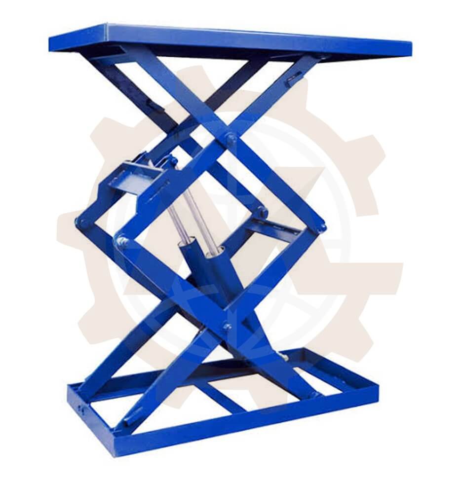
Double and Multi-Stage Scissor Lifts
Stacked scissor stages provide greater vertical travel for a given platform footprint. The design must control cumulative clearance, lateral stiffness, stage synchronization, pivot tolerance, hose routing, buckling, and increased sensitivity to off-center loading. Higher travel also increases the importance of guidance and stability.
Double and Multi-Stage Scissor Lifts
Tandem and Long-Platform Scissor Lifts
Tandem mechanisms support long platforms, vehicles, machinery, or distributed loads using scissor sets arranged along the length. Load sharing is influenced by platform stiffness, manufacturing tolerances, actuator arrangement, pivot alignment, and product position. Mechanical or hydraulic synchronization may be required to prevent racking.

Tandem and Long-Platform Scissor Lifts
Hydraulic Scissor Lift Platforms
Hydraulic cylinders provide high force density and flexible packaging for industrial scissor lifts. The system may use one or several cylinders, direct or levered actuation, and single- or double-acting circuits. Bore, rod, stroke, mounting, pressure, speed, flow, buckling, seals, valves, reservoir, cooling, and emergency lowering are engineered together.

Hydraulic Scissor Lift Platforms
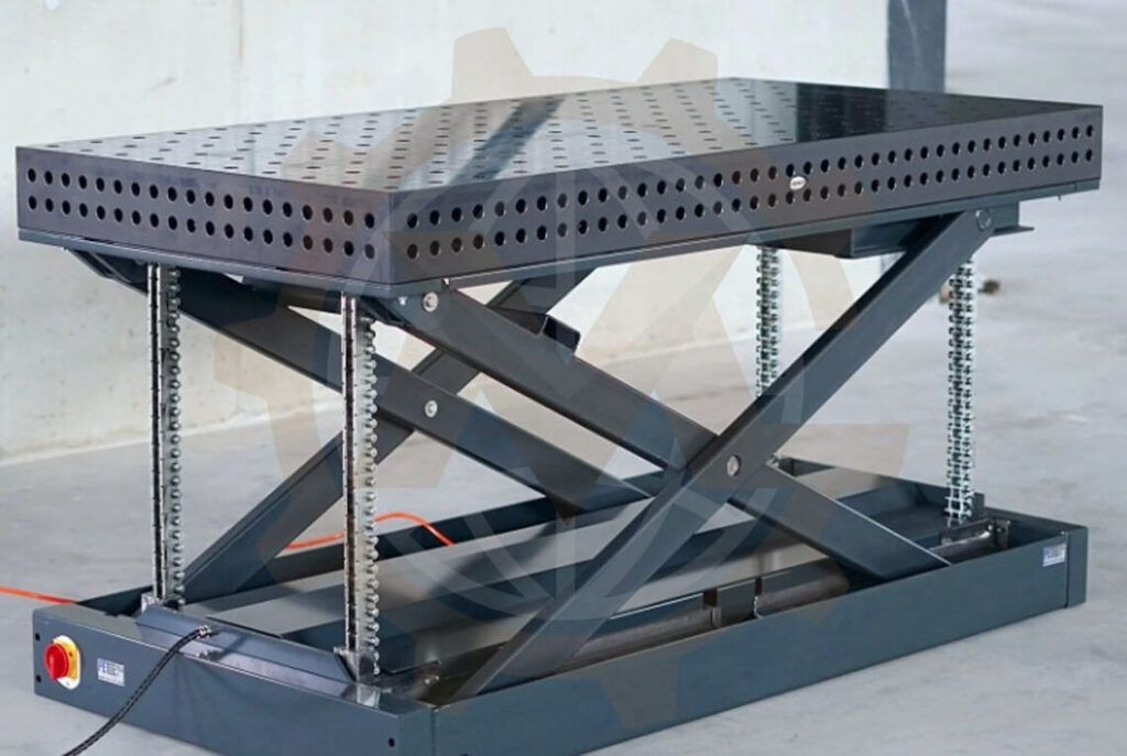
Electromechanical Scissor Lift Tables
Screw jacks, ball screws, electric cylinders, chains, belts, or geared mechanisms can provide clean operation and precise positioning. The design checks actuator thrust, duty, speed, screw buckling, critical speed, brake or self-locking behavior, synchronization, overload protection, and response after power loss.
Electromechanical Scissor Lift Tables
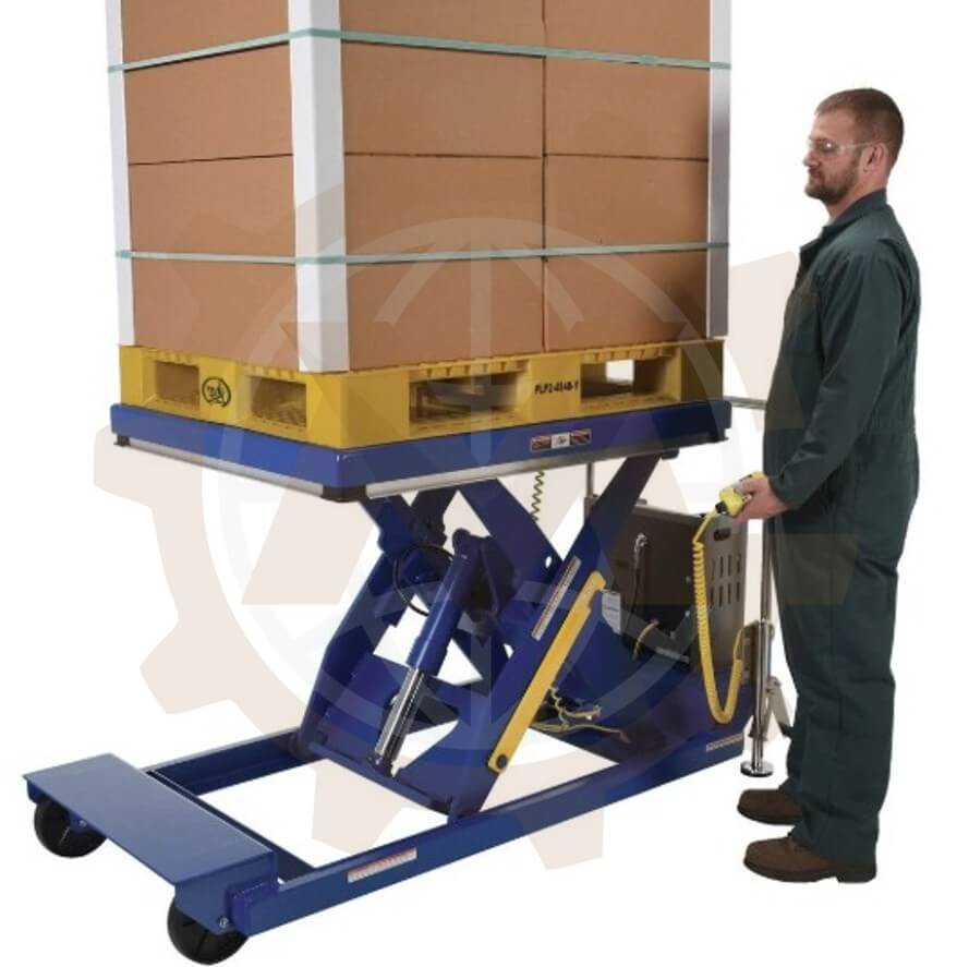
Mobile and Portable Scissor Lift Tables
Mobile units add casters, wheels, steering, brakes, tow points, batteries, or onboard power. Stability must be evaluated for travel, lifting, floor slope, wheel reactions, platform extension, push and pull forces, and accidental movement. A mobile base cannot be treated as a fixed foundation.
Mobile and Portable Scissor Lift Tables
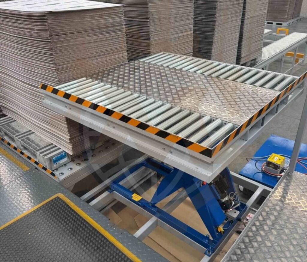
Conveyor-Integrated Scissor Lifts
A scissor lift platform can carry roller, chain, belt, modular, or pallet conveyor equipment to transfer loads between elevations. Conveyor mass, drive torque, cable routing, transfer impact, stopping accuracy, product overhang, and sequencing are included in the moving-load and stability calculations.
Conveyor-Integrated Scissor Lifts
Stainless Steel and Washdown Lift Tables
Food, pharmaceutical, corrosive, and washdown applications may require stainless steel structures, compatible cylinders and bearings, cleanable details, drainage, sealed components, and controlled lubrication. Material selection alone does not make a complete machine hygienic; joints, welds, covers, access, and cleaning validation also matter.
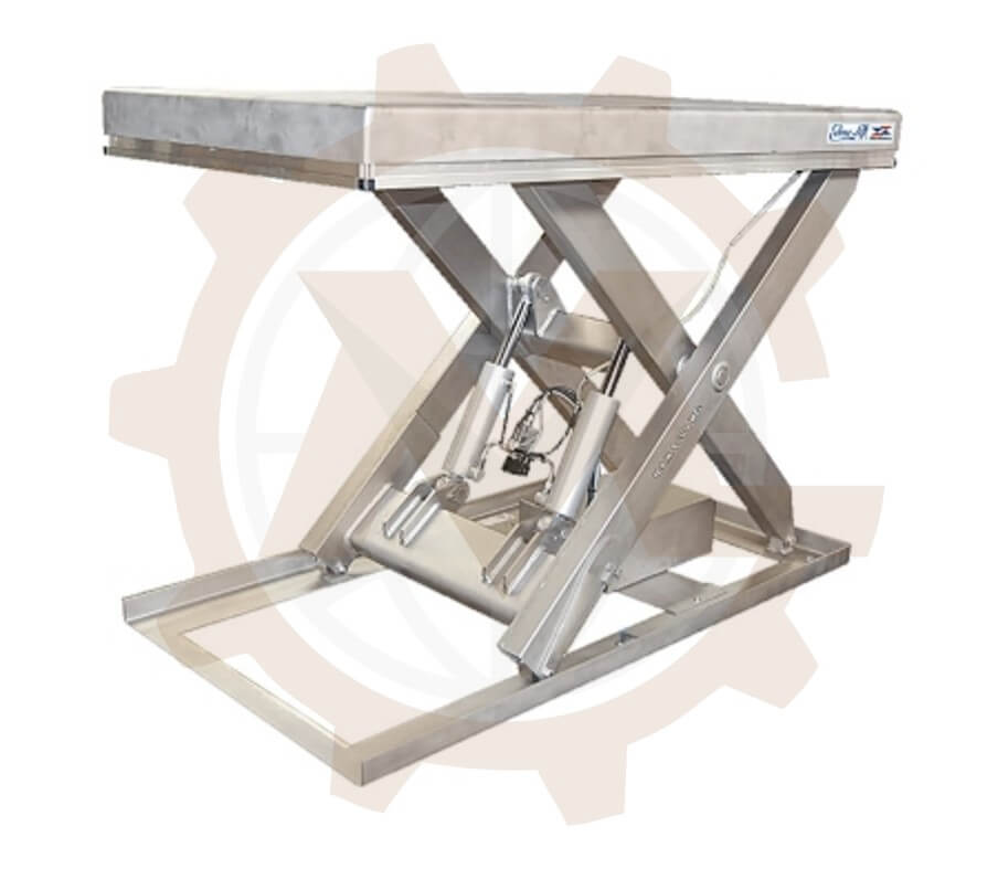
Stainless Steel and Washdown Lift Tables
|
Configuration
|
Typical use
|
Primary design focus
|
|
Single-stage table
|
Ergonomic positioning, pallets and assembly
|
Collapsed height, cylinder force, platform and off-center load
|
|
Double/multi-stage lift
|
High vertical travel in limited footprint
|
Guidance, cumulative tolerance, buckling and stability
|
|
Tandem lift
|
Long platforms, vehicles and machinery
|
Load sharing, platform stiffness and synchronization
|
|
Hydraulic platform
|
Heavy industrial lifting
|
Cylinder sizing, pressure, flow, valves and emergency lowering
|
|
Electromechanical table
|
Clean, accurate or programmable positioning
|
Actuator thrust, duty, screw/drive stability and brakes
|
|
Mobile lift table
|
Flexible material handling
|
Wheel reactions, brakes, floor slope and transport stability
|
|
Conveyor lift
|
Automated vertical transfer
|
Conveyor loads, alignment, cables, controls and cycle time
|
GMD’s Scissor Lift Development Workflow
1. Define the Lifting Mission
We collect minimum and maximum loads, dimensions, center of gravity, support points, travel, collapsed and raised heights, platform size, speed, cycle time, duty, operating hours, loading method, environment, interfaces, and future product variants. Credible conditions such as uneven loading, transfer impact, jammed rollers, or pressure loss are recorded in the design basis.
2. Select the Mechanism Architecture
We establish the number of stages, arm arrangement, fixed and sliding pivots, actuator type, cylinder or screw position, guidance, base, platform, and synchronization method. Concept options are compared using force, stroke, footprint, collapsed height, stability, access, cost, fabrication, and maintenance criteria.
3. Model Kinematics and Operating Envelope
The mechanism is evaluated from its lowest usable angle to maximum height. We calculate arm angles, pivot trajectories, roller travel, actuator stroke, velocity ratio, clearances, platform movement, and swept envelopes. Pinch zones, hose and cable paths, and component interference are reviewed throughout motion—not only at end positions.
4. Calculate Structural and Actuator Loads
Engineering calculations cover platform loads, scissor-arm forces, pivot reactions, roller and rail loads, actuator force, hydraulic pressure or motor torque, pin shear and bending, bushing pressure, arm buckling, weldments, base and platform deflection, stability, anchors, and fatigue where duty requires it.
5. Develop the Detailed 3D Assembly
We model the arms, pivots, pins, bushings, rollers, tracks, cylinder or actuator, base, platform, guides, stops, maintenance supports, hose and cable routing, power unit interfaces, guards, sensors, and connected machinery. Assembly sequence, adjustment, inspection, lubrication, and replacement access are reviewed in 3D.
6. Release Fabrication-Ready Documentation
The production package can include general arrangements, fabricated-frame drawings, arm profiles, machined pins, bushings, roller and track details, cylinder mounting, platform assemblies, guards, mechanical supports, purchased-component specifications, and a complete bill of materials.
7. Coordinate Design Review and Integration
We review the design with the client, fabricator, actuator or hydraulic supplier, and controls team, then incorporate agreed comments under revision control. Optional support includes supplier-data updates, manufacturing clarification, installation-interface changes, and as-built documentation.
Scissor Geometry, Force Peaks, and Actuator Placement
Actuator placement is one of the most consequential decisions in scissor lift design. A cylinder connected close to the lower pivots may fit within a shallow base but can require very high breakaway force at low angle. Moving the attachment point, using a lever, selecting twin cylinders, or increasing the minimum starting angle can reduce force but may increase collapsed height, stroke, or structural complexity.
The design evaluates actuator force at multiple positions using the actual geometry and load cases. Friction, seal resistance, pressure losses, moving mass, acceleration, manufacturing tolerance, and an appropriate design margin are added to the ideal static requirement. The lowest point often governs force, while another position may govern pin, arm, mount, or buckling loads.
|
Design variable
|
Engineering effect
|
|
Minimum scissor angle
|
Controls force peak, collapsed height and sensitivity near start
|
|
Arm length and stage count
|
Determine travel, footprint, slenderness and lateral stiffness
|
|
Actuator attachment points
|
Set force, stroke, mount reactions and packaging
|
|
Platform/load center of gravity
|
Changes arm, roller, guide, base and stability loads
|
|
Fixed/rolling pivot arrangement
|
Controls horizontal movement, rail force and platform path
|
|
Acceleration and speed
|
Affect dynamic force, flow/power, stopping and cycle time
|
|
Manufacturing clearances
|
Influence racking, load sharing, friction and platform play
|
Structural Checks for Arms, Pins, Rollers, and Frames
Scissor Arms
Arms carry a combination of axial compression or tension, bending, local bearing, and secondary loads created by offset joints and imperfect alignment. Checks include yield, buckling, lateral torsional behavior where relevant, net section at pivot holes, fatigue, weld effects, and deflection. Plate thickness alone does not establish capacity.
Pivot Pins and Bushings
Pins are checked for shear, bending, bearing pressure, fatigue, retention, fit, and lubrication. Bushings or bearings are selected for projected area, oscillating motion, surface speed, contamination, temperature, lubrication, and expected life. Replaceable bushings can protect expensive arm plates and simplify overhaul.
Rollers, Wheels, and Guide Tracks
Rolling ends experience concentrated reactions that vary with lift position and offset loading. Roller diameter, material, bearing, shaft, rail thickness, local contact stress, edge distance, alignment, and contamination are considered. Tracks require adjustment and replacement access without weakening the supporting frame.
Base and Platform Structures
The base distributes lift reactions into the floor, machine frame, pit, vehicle chassis, or support structure. The platform must limit deflection to protect load stability and connected conveyors. Crossmembers, deck, edge members, cylinder mounts, guide supports, and anchor zones are evaluated under centered and eccentric loads.
Welded Joints and Fabrication Tolerance
Weld details are developed around force flow, fatigue exposure, distortion, access, inspection, and the selected fabrication process. Pivot bores and guide rails require controlled alignment; welding sequence, machining after fabrication, jigs, shims, or adjustable mounts may be specified to achieve it.
Hydraulic System Sizing and Control Strategy
A hydraulic scissor lift is sized from the maximum required cylinder force across the motion range, not only the rated platform load. Cylinder bore is derived from available working pressure with allowances for losses and margin. Rod diameter is checked for compression and buckling at the actual unsupported length and end conditions. Stroke and closed length are verified against mechanism geometry and installation tolerance.
- Pump flow for target raising speed, including changing velocity ratio and simultaneous cylinders.
- Motor power from pressure and flow, including efficiency, starting, intermittent duty, and thermal load.
- Reservoir capacity, fluid selection, filtration, breathers, temperature, cooling, and contamination control.
- Pressure relief, load-holding or counterbalance valves, hose-burst protection, check valves, and controlled lowering.
- Flow dividers, synchronized cylinders, position feedback, or mechanical equalization for multiple lift points.
- Hose size, pressure loss, bend radius, routing, abrasion protection, fittings, and full-motion clearance.
- Manual or emergency lowering that does not create uncontrolled descent or require unsafe access.
- Pressure switches, transducers, level and temperature monitoring, and maintenance diagnostic points.
Hydraulic safety functions depend on the circuit architecture, cylinder arrangement, risk assessment, and applicable requirements. A check valve alone may prevent reverse flow but does not address every hose, fitting, valve, seal, mechanical, control, or structural failure. Mechanical maintenance supports and verified isolation remain essential for work beneath a raised platform.

Hydraulic System Sizing and Control Strategy
Electric, Screw, and Alternative Actuation
Electric linear actuators and screw-jack systems can provide repeatable positioning without a hydraulic power unit. Selection considers peak thrust, dynamic and static capacity, screw lead, efficiency, critical speed, buckling, duty cycle, thermal limits, brake, back-driving, position feedback, lubrication, and overload protection. Multiple actuators require mechanical shafts, electronic synchronization, or closed-loop position control appropriate to the consequence of mismatch.
Pneumatic cylinders may be useful for light loads or short strokes but compressibility affects stiffness and controlled holding. Chain, belt, cam, or linkage drives can suit specialized mechanisms. The actuation technology is selected from load, travel, speed, accuracy, energy availability, cleanliness, duty, maintenance, and safe-failure requirements.

Electric, Screw, and Alternative Actuation
Platform Stability and Eccentric Load Performance
A scissor mechanism can be stable under a centered static load yet bind, tilt, or overload components when the load is placed near an edge or moves across the platform. Design load cases therefore include longitudinal and transverse eccentricity, rolling loads, transfer impact, personnel movement where permitted, platform extensions, wind or environmental loads when applicable, and accidental foreseeable positioning.
- Platform torsion and local deck loading at wheels, pallet feet, machine mounts, or concentrated fixtures.
- Unequal scissor-set loading caused by load position, platform flexibility, tolerance, or actuator mismatch.
- Base reactions, anchor tension and shear, floor bearing, pit-edge loads, and support-frame deflection.
- Side loading from conveyors, push/pull operations, hoses, cables, guides, bumpers, and connected equipment.
- Stability against tipping, uplift, sliding, caster movement, or structural instability at all lift heights.
- Allowable platform level, lateral play, stopping accuracy, and alignment with transfer or process equipment.
Guidance, Synchronization, and Position Control
The scissor linkage guides vertical travel but does not always provide enough lateral stiffness or positioning accuracy for tall, narrow, tandem, or conveyor-integrated lifts. External guide rails, mast rollers, linear guides, stabilizers, or mechanical constraints may be required. Guidance must avoid over-constraint when the structure deflects or expands.
Synchronization can be achieved through a common platform and stiff structure, mechanically linked shafts or chains, hydraulic flow division, matched cylinders, or electronic position control. The appropriate method depends on platform length, load variation, required level, actuator count, cycle rate, and consequences of racking. End stops are not a substitute for controlled synchronization during travel.
Conveyor and Automation Integration
A lift table under a conveyor becomes part of the material-flow sequence. The carrier must stop at a repeatable transfer elevation, support the conveyor under torque and impact, and confirm that the product is fully inside before moving. Rollers, chains, belts, guides, stops, sensors, cables, hoses, and guards are coordinated with the lift envelope.
- Infeed and outfeed datum, direction, conveyor speed, pitch, product ownership, and transfer permissives.
- Platform stopping accuracy, mechanical support or location, settling time, and level confirmation.
- Product presence, overhang, skew, jam, load-clear, upper/lower position, and overtravel sensing.
- Cable carrier or festoon routing for conveyor motors, sensors, valves, encoders, and safety devices.
- Cycle-time model covering transfer, verification, lift acceleration, travel, deceleration, dwell, and return.
- Recovery after blocked transfer, lost product, pressure or power loss, sensor disagreement, and drive fault.

Conveyor and Automation Integration
Risk Reduction for Industrial Scissor Lifts
Scissor lifts contain severe shear and crushing zones, a raised load, stored hydraulic or mechanical energy, potential uncontrolled descent, and access hazards around the platform. Safety measures must follow a documented risk assessment for the complete machine, intended users, operating modes, environment, country of installation, and connected equipment.
- Fixed, interlocked, or distance guarding around accessible scissor arms, rollers, tracks, pivots, and moving platform edges.
- Toe guards, safety edges, bellows, skirts, rails, gates, interlocks, or presence-sensing devices as appropriate to the access pattern.
- Load-holding and controlled-lowering provisions selected for the actual hydraulic or mechanical architecture.
- Mechanical maintenance props, blocking devices, or supports that secure the platform independently before access beneath it.
- Upper and lower limits, independent overtravel protection, overload detection, and defined stop behavior.
- Emergency stops and restart logic coordinated with connected conveyors, robots, machines, and operator stations.
- Isolation for electrical, hydraulic, pneumatic, gravitational, spring, and other stored energy with practical lockout points.
- Safe access for inspection, lubrication, hose replacement, pin removal, actuator service, and platform adjustment.
Applicable requirements differ between industrial lift tables, mobile elevating work platforms, vehicle lifts, loading equipment, and other machinery categories. Intended use and product classification should be resolved early. GMD can engineer within an agreed design basis, while final certification, installation approval, and jurisdictional compliance require the responsible project parties and qualified assessors.
Durability, Inspection, and Serviceability by Design
Reliability improves when wear and misalignment can be detected before a failure. Pins, bushings, rollers, tracks, arms, welds, cylinders, hoses, fittings, valves, screws, chains, guides, stops, sensors, and anchors need accessible inspection points and defined acceptance criteria. Grease points should be reachable at a safe lift condition and protected from contamination.
- Replaceable bushings, rollers, wear strips, guide pads, hoses, seals, and sacrificial contact components.
- Adjustment for rollers, tracks, guides, sensors, mechanical stops, synchronization, and platform alignment.
- Removal paths and lifting points for cylinders, actuators, arms, pins, power units, platform sections, and guards.
- Visual or measurable wear limits for pins, bushes, rollers, tracks, chains, screws, arms, welds, and hoses.
- Drainage and corrosion protection appropriate to washdown, outdoor, chemical, oily, or dusty environments.
- Maintenance instructions, lubrication schedule, torque data, inspection intervals, spare parts, and controlled drawings.
Where Custom Scissor Lifts Add the Most Value
- Ergonomic lift tables for assembly, welding, packing, inspection, and manual handling.
- Pallet positioning, loading docks, material transfer, turntables, and production-line elevation changes.
- Roller, chain, belt, and modular conveyor lift-and-transfer stations.
- Machinery, molds, tools, fixtures, dies, components, and work-in-process positioning.
- Automotive, battery, appliance, metalworking, warehouse, and general manufacturing systems.
- Food, pharmaceutical, and consumer-product equipment with defined washdown or hygienic needs.
- Vehicle, equipment, maintenance, and access platforms engineered for a clearly defined use case.
- High-travel, low-profile, tandem, stainless, mobile, or otherwise nonstandard lifting requirements.
Scissor Lift CAD, Calculation, and Drawing Package
|
Deliverable
|
Typical content
|
|
Design basis
|
Loads, travel, platform, duty, speed, environment, interfaces, assumptions and requirements
|
|
Concept package
|
Mechanism options, actuator placement, stage count, base, platform and access zones
|
|
Kinematic model
|
Heights, angles, actuator stroke, roller travel, clearances and swept envelopes
|
|
Engineering calculations
|
Arms, pins, bushes, rollers, actuator, hydraulics, frames, stability and cycle time
|
|
3D CAD assembly
|
Mechanism, platform, base, actuator, guides, guards, sensors and interfaces
|
|
2D drawings
|
General arrangement, fabrication, machining, pin, arm and assembly drawings
|
|
Bill of materials
|
Manufactured parts, actuator, hydraulics, bearings, sensors, hardware and guards
|
|
Exchange and review
|
Inventor, STEP, SAT, DXF, PDF, Excel and controlled design-review support
|
Why GMD Is a Strong Scissor Lift Engineering Partner
- More than 10 years of mechanical machine-design experience in lifting equipment, conveyors, automation, and production machinery.
- Analysis built around changing mechanism geometry, worst-case actuator force, eccentric loading, stability, and real operating duty.
- Practical attention to fabrication tolerance, pivot alignment, welding, assembly, adjustment, inspection, and component replacement.
- Autodesk Inventor as the primary design platform, with common neutral CAD and documentation formats available.
- Flexible support for a complete custom lift or as an extension of an OEM, fabricator, or system-integrator engineering team.
- Clear definition of assumptions, exclusions, responsibility boundaries, deliverables, and design-review milestones.
- Remote engineering collaboration for manufacturers and integrators serving US, European, Australian, and other international markets.
Scissor Lift Project Inputs Required for an Accurate Design
- Load drawings, weight range, center of gravity, support points, rolling or concentrated loads, and foreseeable eccentricity.
- Required platform size, travel, collapsed height, raised height, speed, cycle time, duty, and operating hours.
- Fixed, mobile, pit-mounted, floor-mounted, vehicle-mounted, conveyor-integrated, or machine-integrated arrangement.
- Loading and unloading method, operator access, connected equipment, transfer forces, and position accuracy.
- Available hydraulic pressure/flow, electrical power, preferred actuator or components, and control architecture.
- Temperature, water, oil, dust, corrosion, washdown, outdoor exposure, hazardous-area, or cleanliness requirements.
- Installation location, floor or support data, anchors, access, maintenance strategy, target market, standards, CAD formats, and schedule.
Scissor Lift Design Questions Answered
What information is needed to design a custom scissor lift?
The essential inputs are load mass and dimensions, center of gravity, load distribution, platform size, travel, collapsed and raised heights, speed, cycle rate, duty, mounting, loading method, environment, utilities, interfaces, and applicable project requirements.
Why is cylinder force highest near the lowered position?
At a shallow scissor angle, the mechanism has poor vertical mechanical advantage. The actuator may need to create a large horizontal or diagonal force to generate a comparatively small upward force. Exact behavior depends on actuator location and linkage geometry, so force must be evaluated across the complete stroke.
How do you size a hydraulic cylinder for a scissor lift?
Cylinder sizing starts with a kinematic model and the worst required actuator force, including load, platform and moving mass, friction, acceleration, pressure losses, and design margin. Bore, rod buckling, stroke, closed length, mounting reactions, speed, flow, pressure, and duty are then checked together.
What is the difference between a single and double scissor lift table?
A single-stage lift uses one scissor level and normally provides moderate travel. A double or multi-stage design stacks mechanisms to achieve greater height, but requires additional attention to lateral stiffness, cumulative tolerance, buckling, guidance, synchronization, and stability.
Can a scissor lift carry a conveyor?
Yes. The platform can support roller, chain, belt, or modular conveyors when their mass, drive forces, transfer impact, product load, cabling, alignment, stopping accuracy, sensors, guarding, and sequence are included in the design.
How are off-center loads handled?
The platform, arms, pivots, rollers, guides, base, and anchors are checked for defined longitudinal and transverse eccentric-load cases. Platform stiffness, dual-mechanism load sharing, external guidance, and synchronization may be required to keep tilt and component loading within acceptable limits.
Does a hydraulic valve make a raised scissor lift safe for maintenance?
Not by itself. Hydraulic components can reduce uncontrolled movement, but maintenance beneath a raised platform generally requires verified isolation and an independent mechanical support or blocking method appropriate to the machine and risk assessment.
Can GMD redesign or verify an existing scissor lift?
Yes, when sufficient drawings, measurements, material data, component specifications, loads, duty, and operating history are available. The scope can review kinematics, actuator force, pins, arms, rollers, guides, platform, base, hydraulics, stability, access, and known failure modes.
Which CAD deliverables can GMD provide?
Depending on scope, GMD can provide concept layouts, kinematic and engineering calculations, 3D assemblies, fabrication and machining drawings, assembly drawings, bills of materials, and agreed formats such as Autodesk Inventor, STEP, SAT, DXF, PDF, and Excel.
How long does scissor lift design take?
Schedule depends on concept maturity, capacity, travel, number of stages, actuator system, safety and interface complexity, calculation depth, documentation level, supplier data, and review cycles. GMD can propose milestones after the inputs and deliverables are defined.
Turn Your Lift Requirement into a Manufacturing-Ready Design
A successful scissor lift begins with accurate load cases and a mechanism geometry that is evaluated throughout its motion. Share your payload, center of gravity, platform dimensions, height range, cycle requirements, mounting constraints, utilities, environment, and required documentation. GMD Services will help convert those inputs into a coordinated concept and a fabrication-ready mechanical design package.
Contact GMD Services to discuss Scissor Lift Design Services for a new industrial lift table, conveyor lift, custom work platform, equipment redesign, capacity verification, or detailed manufacturing documentation.