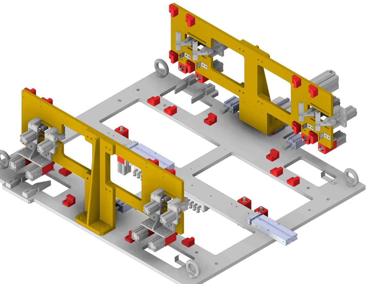
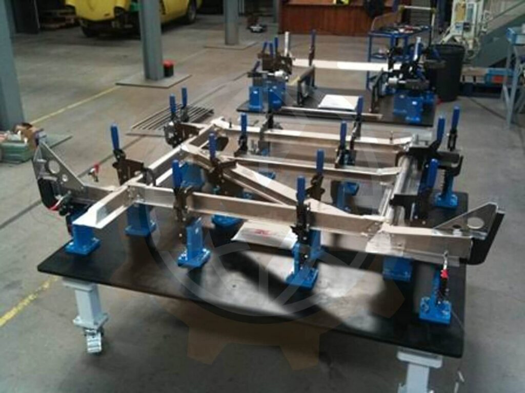
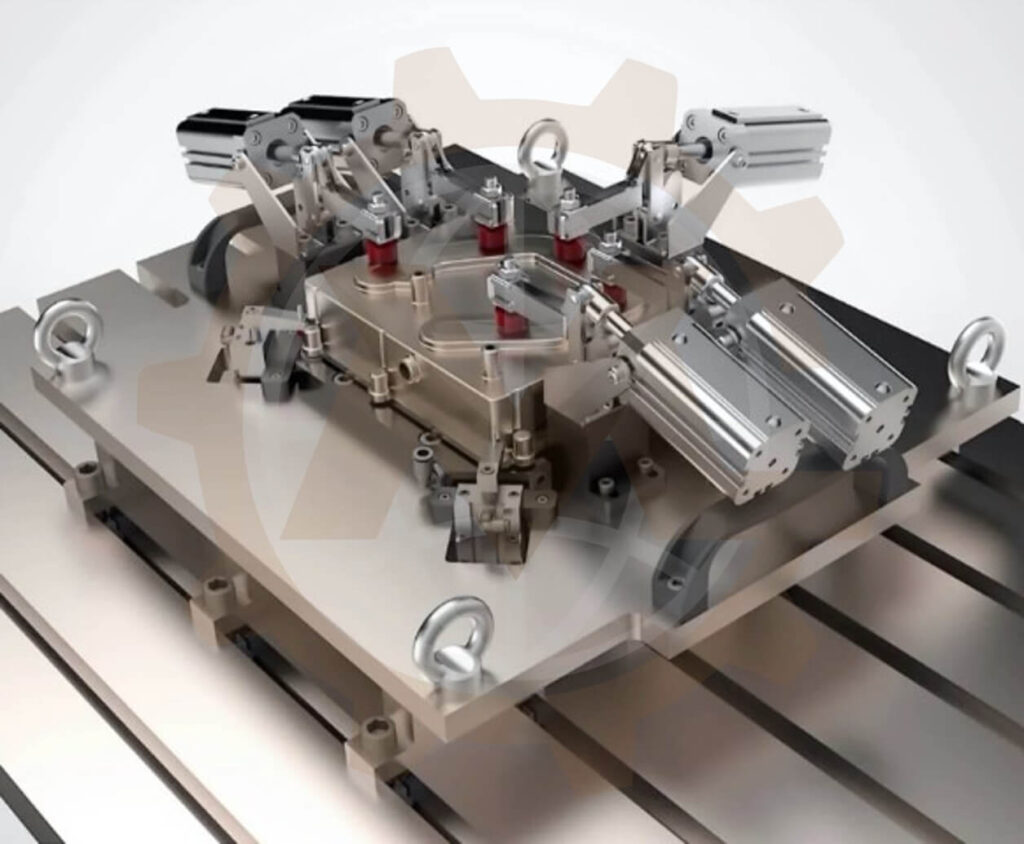
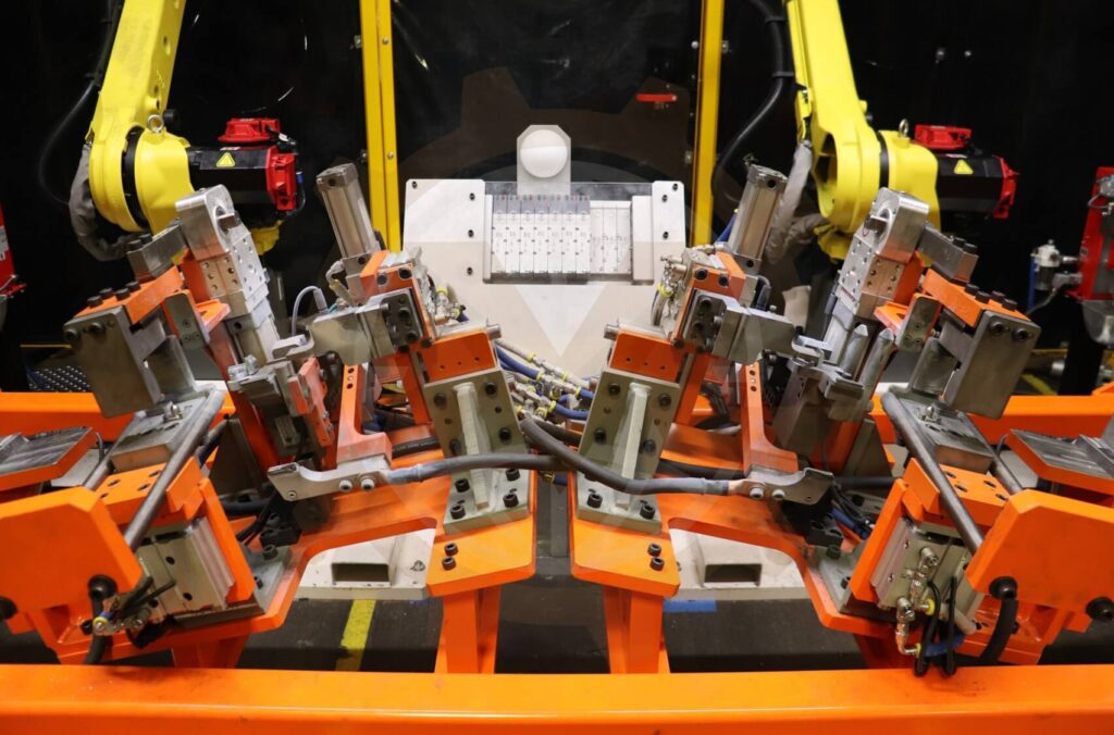
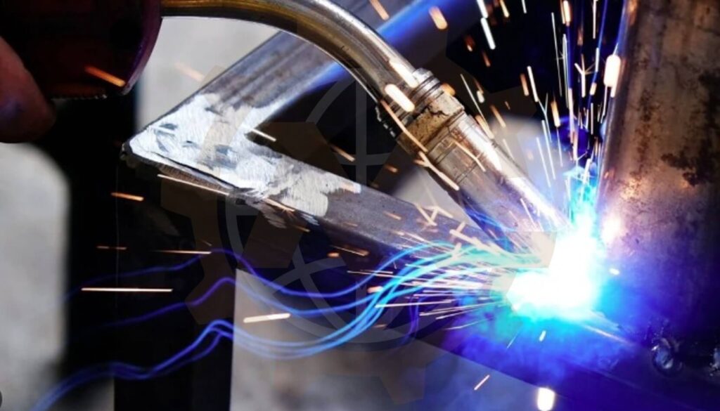
Custom welding jigs and fixtures designed for repeatable part positioning, practical clamping and clear access to every required weld joint.
GMD Engineering develops mechanical tooling for manual, semi-automatic and robotic welding. From locating concepts and pneumatic clamping to detailed 3D CAD, manufacturing drawings and BOMs, we design fixtures around your product geometry, welding process and production requirements
Custom Welding Fixture Engineering for Your Production Process
A welding fixture must do more than hold components together. It must establish the correct assembly position, accommodate real incoming-part variation and allow the welding process to reach the joint. Operators must also be able to load parts, engage clamps and remove the finished assembly without unnecessary handling.
GMD provides welding jig and fixture design services for manufacturers, fabrication companies, machine builders and automation integrators. We develop tooling around your component drawings, critical dimensions, weld locations and production workflow.
The service can cover a dedicated manual weld jig, pneumatic tooling for repeat production, or robotic welding fixtures integrated with a positioner and loading station. Each project is scoped around the mechanical design, documentation and verification needed to support fabrication and integration.
We can also review existing tooling where loading is difficult, clamps obstruct the torch or product changes require a revised fixture.
What Is a Welding Jig or Welding Fixture?
A welding fixture locates and holds separate components in the required relationship during assembly, tack welding or final welding. Typical elements include a base plate, supports, locating pins, stops and clamps.
Although a jig traditionally guides a tool and a fixture primarily holds the workpiece, manufacturers often use welding jig, weld jig and welding fixture interchangeably. Here, these terms describe tooling that positions and secures components for welding.
A custom fixture can support repeatable setup and reduce dependence on manual measurement. Its suitability depends on the product, incoming-part condition and welding process. Fixture accuracy alone does not guarantee the final dimensions of the welded assembly.
Our Welding Jig and Fixture Design Services
Manual Welding Jigs
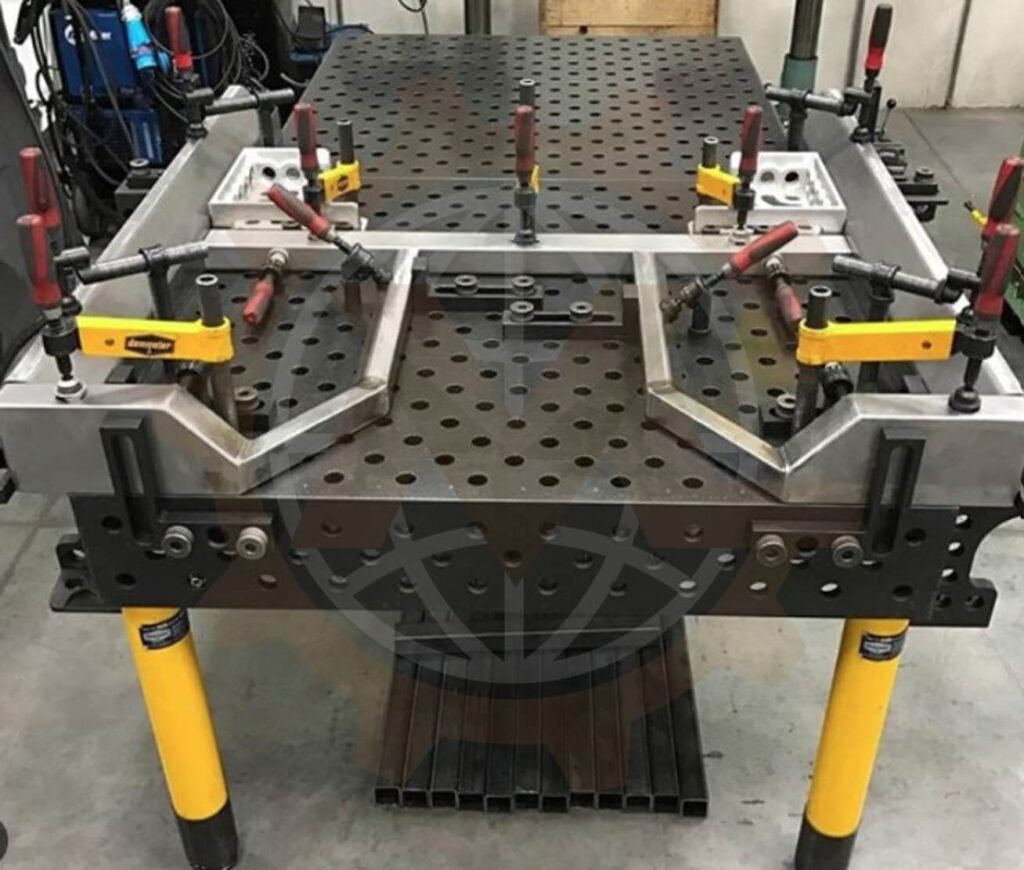
We design fixtures where an operator loads, positions, clamps and welds the components. These may use toggle clamps, screw clamps, removable stops and mechanically operated locating features.
The design considers loading order, hand access, joint visibility and release after welding. For small batches, simple dedicated tooling may be more practical than a powered system
Manual Welding Jigs
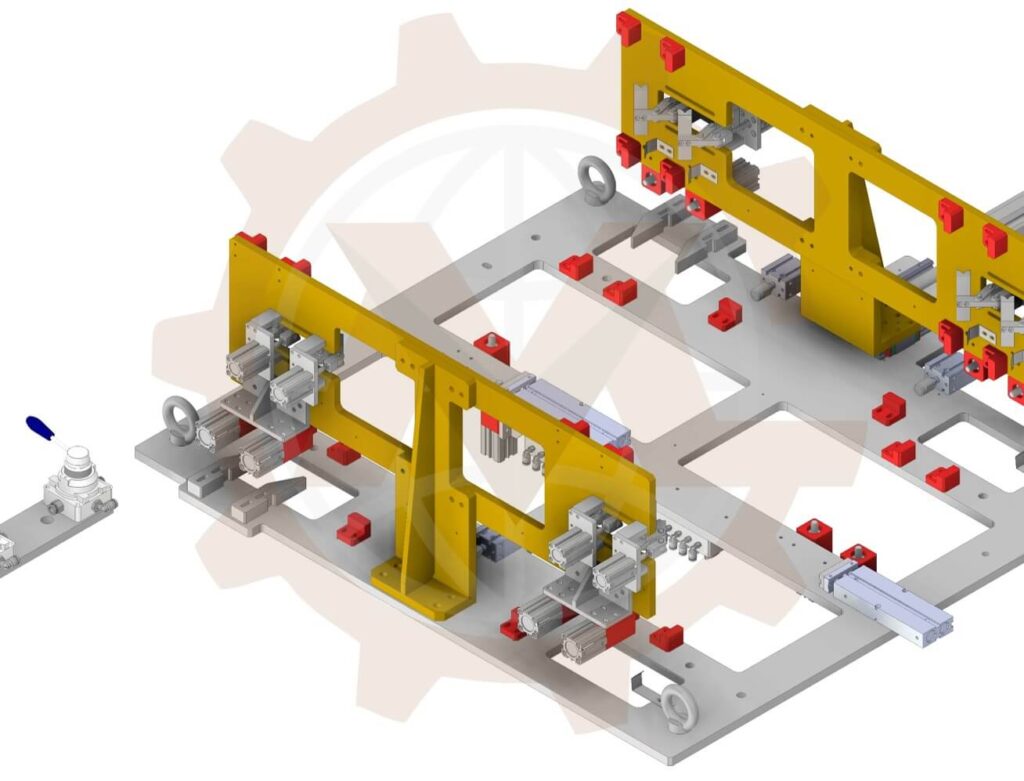
Pneumatic Welding Fixtures
Pneumatic clamping can support repeat production and reduce manual clamp handling. Our mechanical scope may include clamp units, cylinders, linkages, retractable locators and sensor brackets.
Selection considers required force, available pressure, stroke, holding behavior and access. Pneumatic circuits, controls and behavior during pressure loss are separately defined where required.
Pneumatic Welding Fixtures
Robotic Welding Fixtures
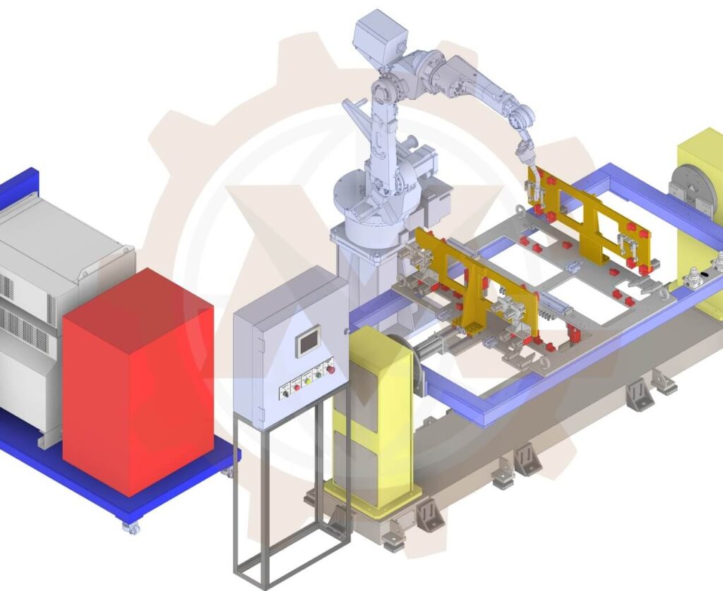
Robot welding fixtures need consistent workpiece location and space for the torch, wrist and robot arm. We review clamp arrangements against the selected robot, tool geometry and required joint access.
The mechanical package may include bases, locators, pneumatic clamps, sensor mounts, utility-routing provisions and positioner interfaces. Geometric access checks support integration planning; robot programming, detailed path simulation and validated cycle-time studies are included only when agreed.
Some products require fit-up and tack welding before final welding elsewhere. We develop tooling that establishes the assembly relationship, exposes tack locations and provides a release path for transfer.
The concept is coordinated with the proposed tack sequence and handling method. Where relevant, we review how the assembly remains stable after removal.
Tack Welding and Assembly Fixtures
Welding Table Fixtures and Modular Tooling
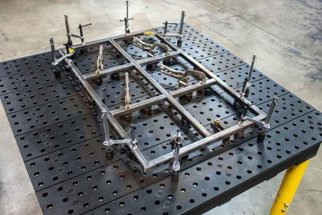
We design custom stops, risers, nests and locating brackets for an existing welding table or fixture plate. The hole pattern, mounting system, surface condition and load capacity are reviewed before design.
Modular tooling can support changing work, while dedicated locating elements may be needed for product-specific geometry or repeatability requirements. A hybrid solution can combine a reusable base with interchangeable tooling.
Welding Table Fixtures and Modular Tooling
Welding Fixture Plates and Structural Bases
Base design considers product weight, support spacing, clamping reactions and mounting loads. Construction is selected around stiffness, fabrication access, machining and handling requirements.
For fabricated bases, drawings can identify post-weld machining of precision surfaces. Plate thickness is selected from the load path and permitted deflection rather than a universal rule.
Positioner and Rotary Fixture Interfaces
We design mounting arrangements for selected welding positioners, rotary tables and headstock-tailstock systems. These may include adapter plates, support frames and removable tooling interfaces.
Checks consider combined mass, center of gravity, mounting loads and supplier torque and moment limits. Payload mass alone does not establish positioner compatibility.
Positioner and Rotary Fixture Interfaces
Fixture Redesign and Product Change Support
We revise tooling for new product revisions, improved access, additional variants or changed welding equipment. Existing bases are reviewed before reuse.
Possible changes include replaceable locators, revised clamp positions and retractable elements. We assess production issues using drawings, measurements and feedback rather than assuming the fixture is the only cause.
Engineering Details That Determine Fixture Performance
Datum Selection and Part Location
We establish how each component is located and how the locating scheme relates to critical finished dimensions. References may include surfaces, holes, edges, pins and stops.
For suitable rigid components, a 3-2-1 locating approach is a useful starting point. Flexible sheet and irregular weldments may need different support arrangements. The goal is to restrain necessary movement without overconstraint or forced assembly.
Clamping Force and Support Placement
Clamps should seat components against the intended supports without deforming them. We consider clamp direction, contact area, unsupported spans and part stiffness.
Required force depends on fit-up and the process. More force cannot compensate for unsuitable locating geometry or inconsistent incoming parts. Calculations are based on the actual mechanism and operating conditions where required.
Torch Access and Weld Visibility
Locators and clamps must leave room for the welding tool and its approach. We review weld locations, torch geometry, clamp-open positions and nearby structures.
Manual tooling also needs practical visibility and operator access. Robotic tooling requires coordination with the robot envelope, with final paths confirmed by the integrator.
Torch Access and Weld Visibility
Heat Effects and Distortion Management
Welding introduces heating and shrinkage. A fixture can support a distortion-control strategy, but restraint may increase residual stresses and the product may move when released.
We coordinate restraint and release arrangements with the client’s welding engineer. Tack sequence, weld sequence, heat input and trial results inform the final process. Presetting or compensation should be based on suitable analysis or trials rather than an assumed allowance.
Loading and Finished-Part Removal
We review loading order, clamp sweep, insertion clearances and removal direction, including interference from the completed weldment.
Retractable pins, removable stops or swing-away elements can provide a release path. Handling provisions for heavy or awkward assemblies are considered within the agreed scope.
Wear and Welding Spatter
Frequently used locating details may need replaceable pins, wear pads and protected contact surfaces. Mechanisms should remain accessible for cleaning and adjustment.
We consider shields and component placement where spatter could impair operation. Materials, hardness and surface treatment are specified for the application where needed.
Wear and Welding Spatter
Welding Current Return and Utility Interfaces
The mechanical layout provides space for the agreed welding current-return connection and process utilities. Electrical requirements are defined by the welding specialist and coordinated with fixture and positioner interfaces.
Routing provisions should help avoid unintended current paths through sensitive components. Final electrical connections and verification remain part of the relevant integration scope.
What Tolerances Should Be Used for a Welding Fixture?
There is no single tolerance suitable for every weld fixture. Tooling accuracy depends on the finished assembly drawing, datum scheme, incoming-part variation, wear and welding process.
We start with critical finished-product dimensions and work backward through the locating scheme. Tighter control is applied where it contributes to those dimensions; noncritical details use practical manufacturing tolerances.
The review may consider:
Accuracy of the product’s locating holes and surfaces.
Clearance or fit between components and locating pins.
Relative position of supports and stops.
Adjustment, shimming and setup provisions.
Welding movement and clamp-release timing.
Inspection in the clamped or free state, as specified.
Fixture repeatability, tooling manufacturing accuracy and finished-product tolerance are related but different requirements. We document them separately where required. Final capability is established through suitable inspection and welding trials.
Dedicated or Modular Welding Fixtures
Dedicated tooling is designed for one assembly or defined family. Modular tooling uses reusable elements that can be repositioned for different products.
Dedicated welding fixtures can simplify repeat loading and provide product-specific access. Modular welding table fixtures can suit prototypes, changing work or smaller batches. Hybrid systems combine reusable bases with dedicated nests.
We compare product variation, batch size, changeover frequency, repeatability, equipment and service life. The most complex solution is not automatically the most economical one.
Applications for Custom Welding Fixtures
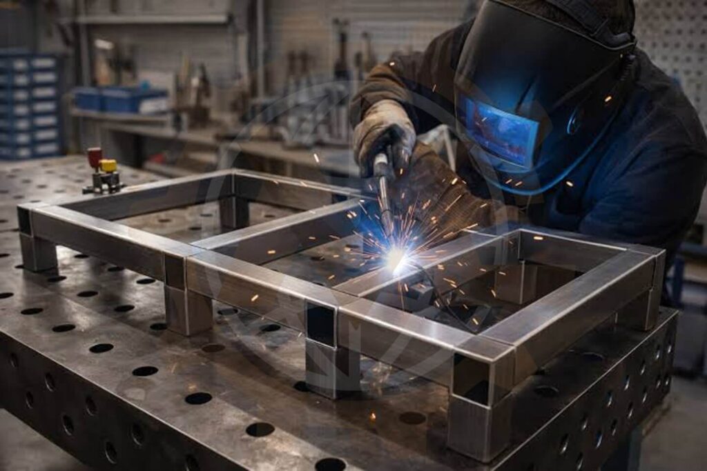
Frames and Fabricated Structures
Locating and clamping for machine frames, supports, brackets and fabricated assemblies, coordinated with inspection datums and the proposed weld sequence.
Frames and Fabricated Structures
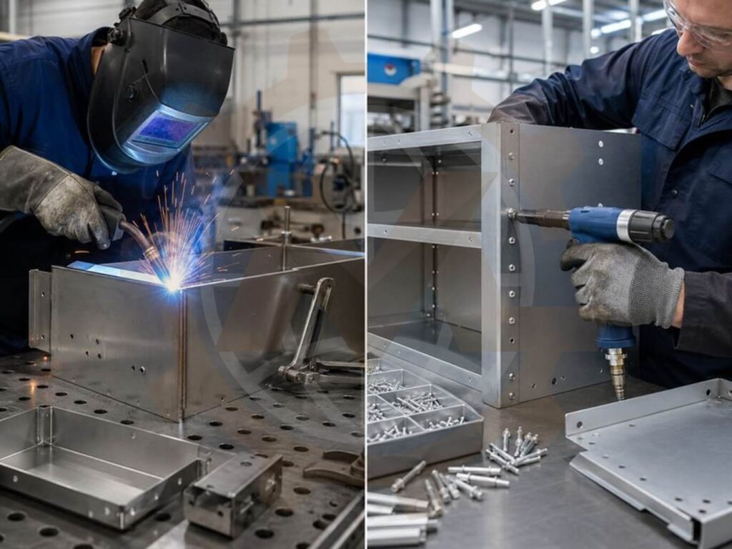
Sheet Metal Assemblies
Tooling for enclosures, panels and formed parts where thin material, support spacing and incoming-part variation affect fit-up.
Sheet Metal Assemblies
Tube and Profile Assemblies
Support geometry and anti-rotation arrangements for tubes and structural profiles, selected around the section shape and required joint access.
Repeated Industrial Components
Dedicated or interchangeable tooling for recurring subassemblies and equipment parts in manufacturing and automation systems.
Material-specific requirements for steel, stainless steel and aluminum are reviewed with the process team, including contact materials and contamination controls where relevant.
Our Welding Fixture Design Process
1 Review Product and Process Requirements
We review CAD files, drawings, weld information and production targets. Critical dimensions, incoming-part conditions and available equipment establish the design basis.
2 Develop the Locating and Clamping Concept
We define datums, loading order, supports and clamps. Concept reviews compare access, handling, complexity and changeover needs before detailed modeling.
3 Create the Detailed CAD Assembly
We develop the base, locators, clamp mechanisms and purchased components in Autodesk Inventor. Table, positioner and surrounding-equipment interfaces are included as agreed.
Create the Detailed CAD Assembly
4 Review Loads and Accessibility
Checks may include clamp forces, support reactions, stiffness, fasteners, positioner loading and geometric interference. Specialist analysis and detailed robot simulation are separately scoped where needed.
5 Prepare Manufacturing Documentation
We prepare part drawings, assembly drawings and BOMs. Critical fits, materials, treatments and setup adjustments are identified where required.
6 Support Fabrication and Trial Feedback
Agreed design support can continue through fabrication, assembly and initial trials. Trial-driven revisions are reviewed against the requirements and revision arrangements.
Welding Fixture Design Deliverables
The final package is agreed before work begins and may include:
Deliverable
Typical contents
3D CAD assembly
Fixture layout and agreed equipment interfaces
Part models
Plates, supports, locators and custom clamp details
Manufacturing drawings
Dimensions, tolerances, materials and treatments
Assembly drawings
Arrangement, item references and assembly details
Bill of Materials
Manufactured parts, purchased items and quantities
Interface drawings
Table or positioner mounting dimensions
Setup information
Datum identification and adjustment guidance
Review records
Agreed calculations and design checks
Exchange files
STEP, PDF, DWG or DXF as specified
CAD version, drawing standards, naming and source-file ownership are confirmed in the proposal. Physical manufacture, installation, robot programming, welding procedure qualification and production validation are included only where expressly agreed.
Explore our semi-automatic robotic welding station case study for an example involving fixtures, pneumatic clamping and rotary positioning equipment. It shows the relationship between workholding and station layout.
We consider how tooling will be fabricated, assembled, adjusted and maintained. Models and drawings connect the concept with the fabrication team’s requirements.
Tooling and Equipment Interfaces Reviewed Together
Our mechanical design services also cover custom machines and robotic cells. Fixtures can be considered alongside loading stations, positioners and surrounding equipment within the agreed scope.
Clear Scope and Review Stages
We define inputs, deliverables, review points and responsibilities before detailed work, giving production, welding and integration teams a shared basis for design review.
Remote Engineering Collaboration
We collaborate through CAD exchanges, drawing reviews and documented feedback. Product information is handled under the agreed confidentiality and access arrangements.
Existing tooling photographs and production issues.
Required CAD version, outputs and schedule.
If the product or process is still developing, we can define an initial concept stage before the full tooling package.
Frequently Asked Questions
Can you design a welding jig from existing CAD files?
Yes. We review models, drawings and weld requirements before developing the concept. Missing inputs and assumptions are identified during the requirements stage.
Do you design manual and robotic welding fixtures?
Yes. Tooling is adapted to the process. Manual fixtures emphasize operator access; robot fixtures also require coordination with the tool and robot envelope.
Can you design tooling for my existing welding table?
Yes. Provide the table model or verified dimensions, hole pattern, mounting system and load limits so we can develop the interface.
How does a welding fixture differ from a checking fixture?
A welding fixture holds components during welding. A checking fixture supports inspection against defined requirements. Heat exposure, loading and inspection access can require different designs.
Can one weld fixture handle several variants?
It can where geometry and production requirements allow. Options include interchangeable nests, adjustable locators and removable modules, with defined changeover and verification steps.
Can a fixture eliminate welding distortion?
It cannot guarantee this alone. Distortion depends on product geometry, fit-up, welding and restraint. The fixture supports a control strategy assessed through process development and trials.
How much clamping force is needed?
Force depends on stiffness, supports, fit-up and mechanism geometry. It is selected for the application; excessive force may deform the product.
Can you include pneumatic clamps and sensors?
Yes. Mechanical scope can include clamp units, cylinders, linkages and sensor mounts. Circuits and controls are agreed separately where required.
Can you design a fixture for a welding positioner?
Yes. We assess its interface, payload, center-of-gravity limits and rated moments or torques against the combined workpiece and tooling loads.
Do you deliver drawings and a BOM?
Yes, when included in the package. These identify custom parts, standard components and the information required for manufacture and assembly.
Can you improve an existing welding jig?
Yes. We review drawings, measurements and production feedback. The solution may combine tooling revisions with incoming-part or process changes coordinated with your team.
How much does welding fixture design cost?
Cost depends on complexity, locating requirements, clamps, automation, interfaces and documentation. Send representative CAD and requirements for a project-specific proposal.
Need a welding jig that fits your product, production process and fabrication requirements?
Send GMD your models, assembly drawings and welding requirements. We will help define a practical scope for new tooling, robotic welding fixtures or an upgrade to existing equipment.
We use cookies to make our website work, analyse traffic and improve your experience. You can accept all cookies, deny non-essential cookies or manage your preferences. You can change your choice at any time. For more information, please see our Cookie Policy.
Functional
Always active
The technical storage or access is strictly necessary for the legitimate purpose of enabling the use of a specific service explicitly requested by the subscriber or user, or for the sole purpose of carrying out the transmission of a communication over an electronic communications network.
Preferences
The technical storage or access is necessary for the legitimate purpose of storing preferences that are not requested by the subscriber or user.
Statistics
The technical storage or access that is used exclusively for statistical purposes.The technical storage or access that is used exclusively for anonymous statistical purposes. Without a subpoena, voluntary compliance on the part of your Internet Service Provider, or additional records from a third party, information stored or retrieved for this purpose alone cannot usually be used to identify you.
Marketing
The technical storage or access is required to create user profiles to send advertising, or to track the user on a website or across several websites for similar marketing purposes.