Mechanical engineering services / Welding Station Design
Welding Station Design Services
Custom welding stations designed around your product, operator workflow and production targets—from practical manual workstations to semi-automatic and robotic layouts.
GMD Engineering develops welding station layouts and mechanical designs that bring together fixtures, positioning equipment, support structures and material handling. We provide 3D CAD models, manufacturing drawings and BOMs to support fabrication and system integration.
Welding Workstations Built Around the Production Task
A welding station is the working environment around the weld. Its performance depends on how parts arrive, how they are positioned, how the welds are accessed and how the finished assembly leaves the station.
A strong fixture can still be difficult to use if the loading area is cramped. A suitable positioner may offer limited value if operators cannot reach the clamps. Poor equipment placement can add handling steps and make maintenance unnecessarily difficult.
GMD provides welding station design services for manufacturers, fabrication companies, machine builders and automation integrators. We develop mechanical layouts that connect product handling, workholding and welding access in one coordinated workstation.
Projects can include a new manual welding bench, a semi-automatic station with pneumatic clamping, a positioner-based workstation or a robotic welding station. We can also redesign existing layouts to accommodate revised products, equipment changes or production problems.
The design scope is defined around your process requirements, available equipment and manufacturing deliverables.
What Does Welding Station Design Include?
Welding station design establishes the layout, mechanical equipment and interfaces needed to perform a defined welding operation. Depending on the application, it can include:
Workstation layout and equipment locations.
Welding table, bench, base or structural frame.
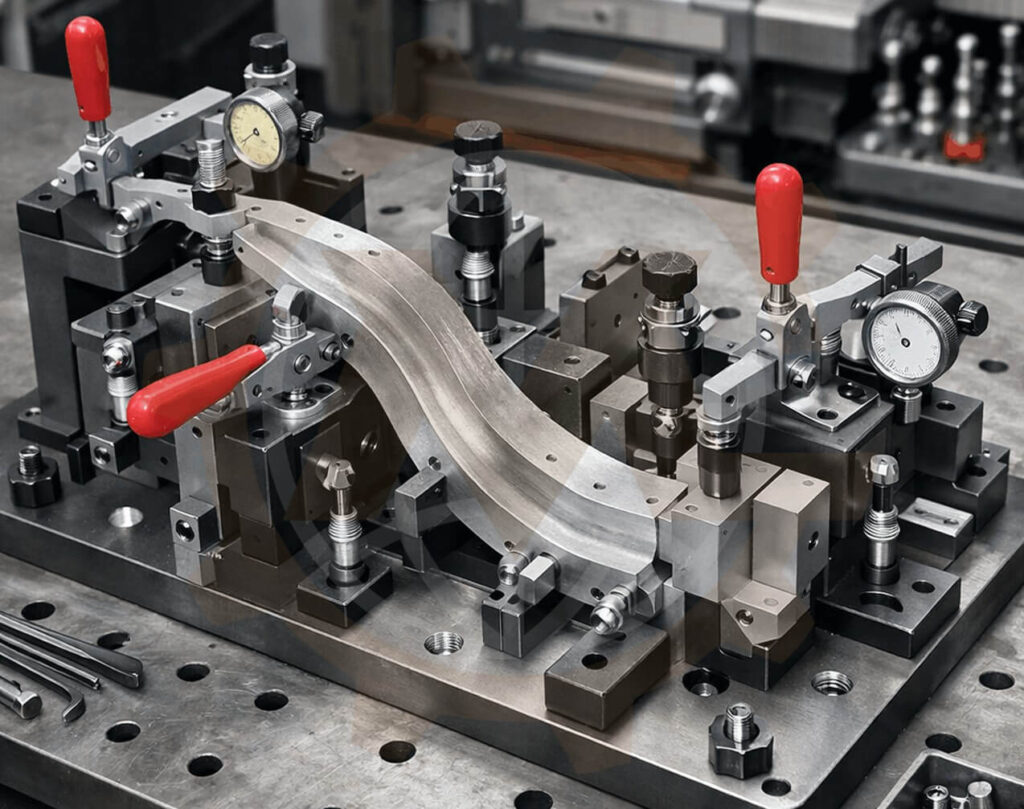
Fixture mounting and clamping arrangements.
Rotary, tilting or indexing mechanisms.
Loading and unloading areas.
Part presentation, transfer and handling provisions.
Welding screens, booth structures or enclosure interfaces.
Mounting space for extraction equipment and process utilities.
Operator access and maintenance clearances.
CAD models, drawings and BOMs.
The fixture controls the workpiece; the station connects that tooling to the wider production task. Where robot motion defines the overall layout, the project also interfaces with robotic cell engineering.
Our Welding Station Design Services
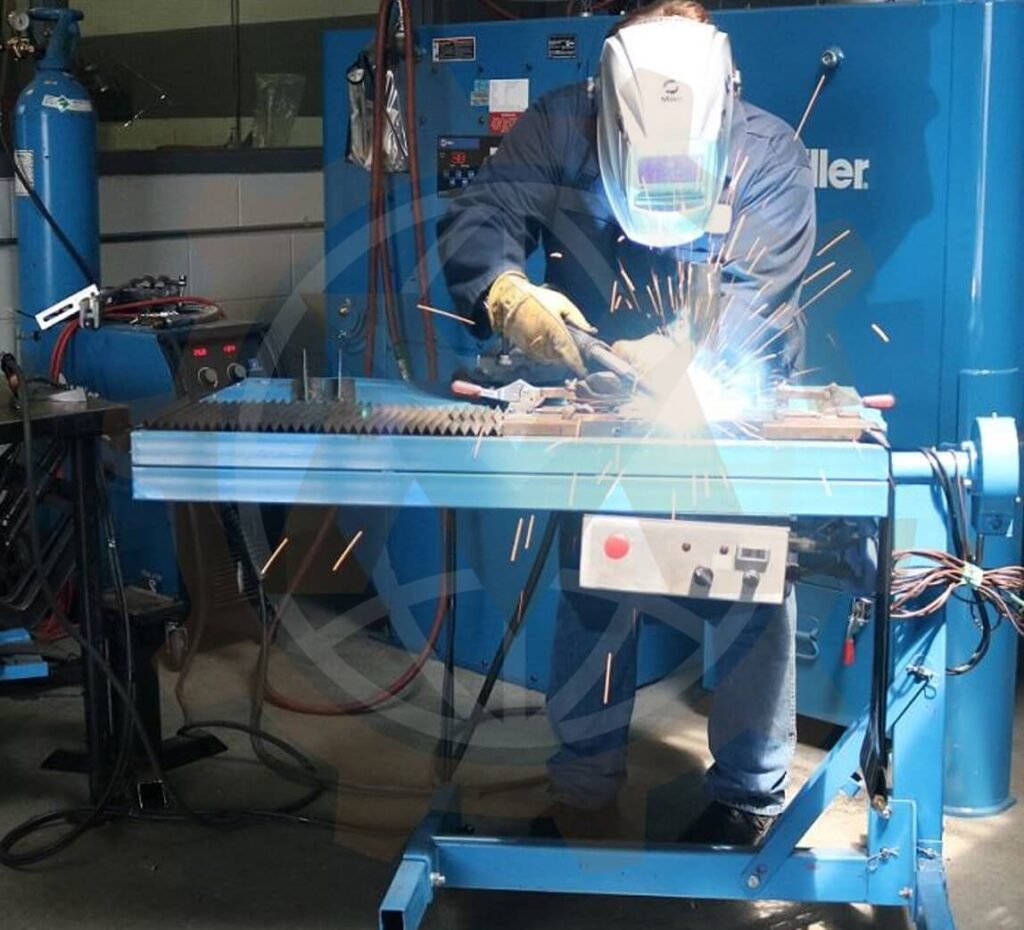
Manual Welding Station Design
We design manual workstations for operations where the operator loads, clamps and welds the assembly. The layout considers product size, work height, joint visibility and the space needed to move the torch.
Mechanical features may include a custom welding bench, fixture base, component racks, tool supports and provisions for handling aids. The objective is a practical setup suited to the task and the people using it.
Manual Welding Station Design
Semi-Automatic Welding Station Design
Semi-automatic stations combine operator tasks with powered functions. These may include pneumatic clamps, product positioning, indexing or controlled part transfer.
We develop the mechanical arrangement and document the intended sequence for coordination with controls engineers. Sensor mounts, cylinder interfaces and access for adjustment can be included. The division between manual and automatic operations is agreed during concept development.
Semi-Automatic Welding Station Design
Positioner-Based Welding Workstations
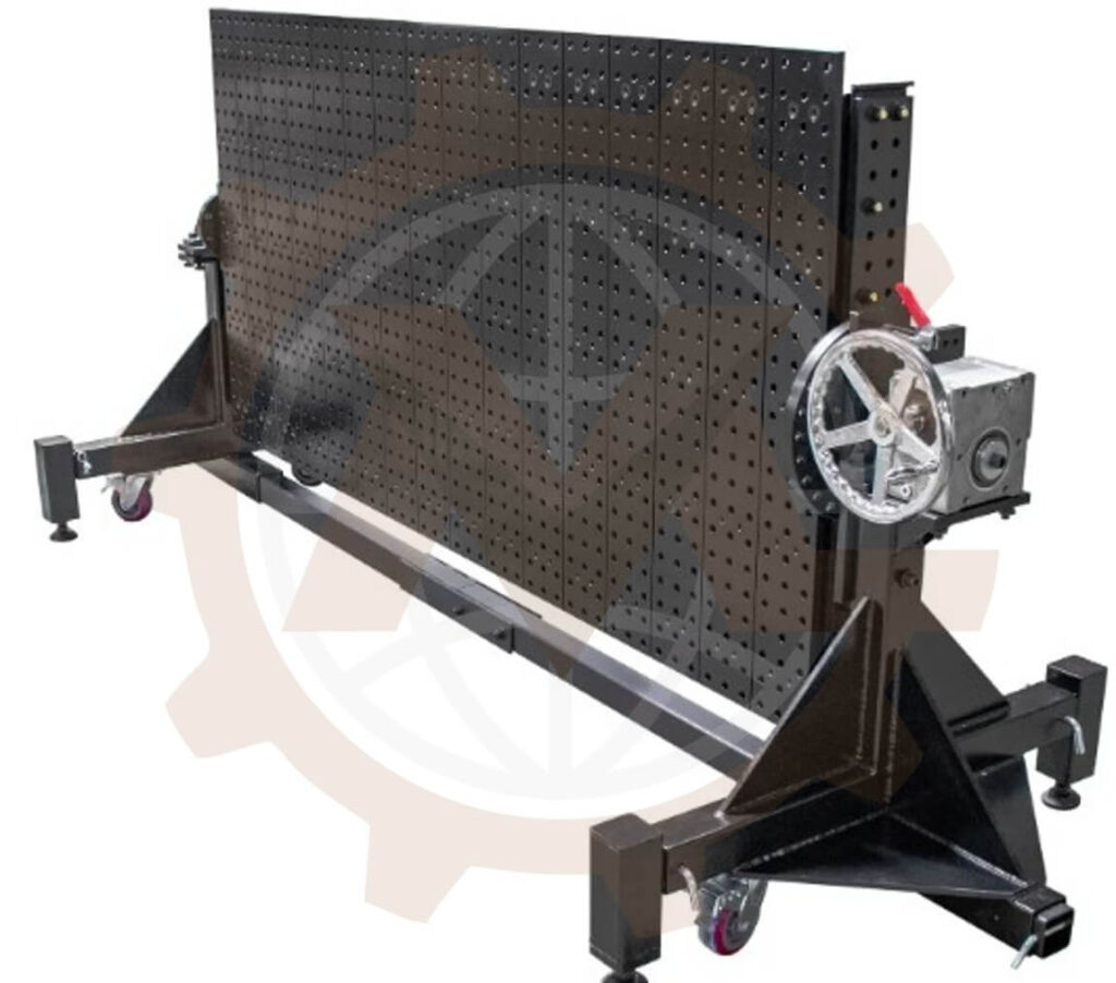
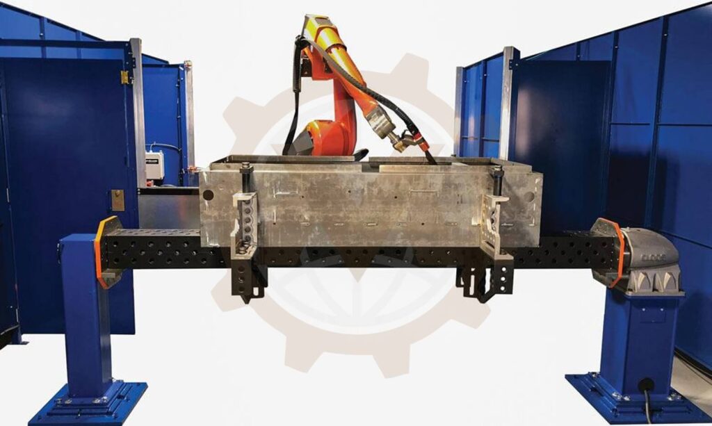
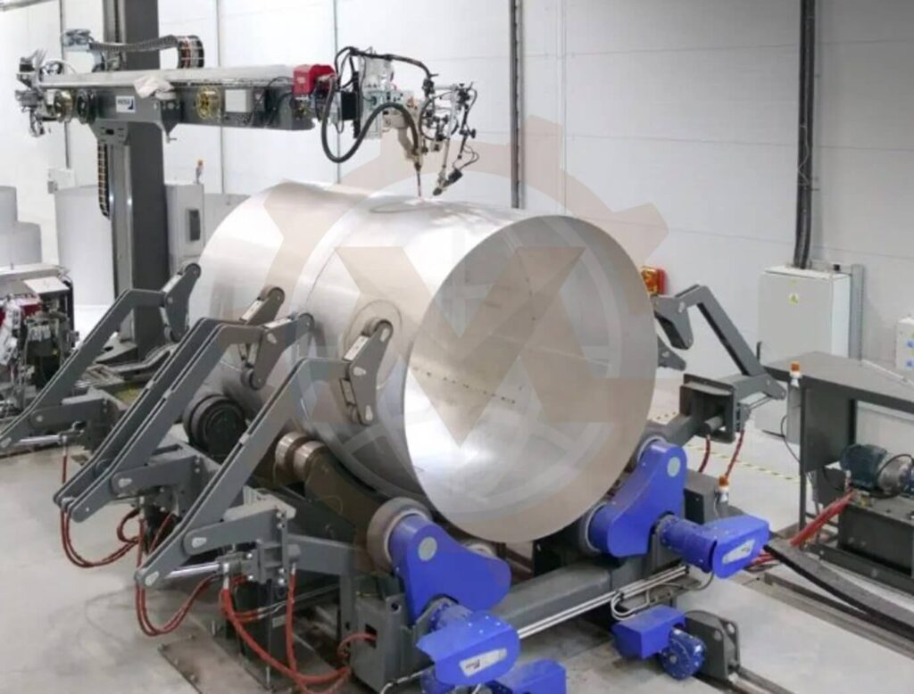
Rotating or tilting a workpiece can improve access to selected joints and reduce repeated manual repositioning. We design workstation arrangements around the selected positioner and its approved operating range.
The layout considers the complete swept envelope, fixture mounting, loading position and access for maintenance. Equipment selection reviews the combined fixture and product mass, center of gravity and supplier moment or torque limits.
Positioner-Based Welding Workstations
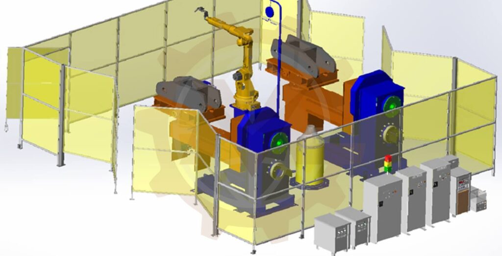
Dual-Station Welding Layouts
A dual-station layout may allow loading at one location while welding takes place at another. Concepts can use separate fixtures, indexing equipment or an exchange arrangement.
We assess how parts move between the loading and welding zones and what separation the operating concept requires. Concurrent loading and welding are adopted only where the process and validated protective system permit them.
Dual-Station Welding Layouts
Rotary Indexing Welding Stations
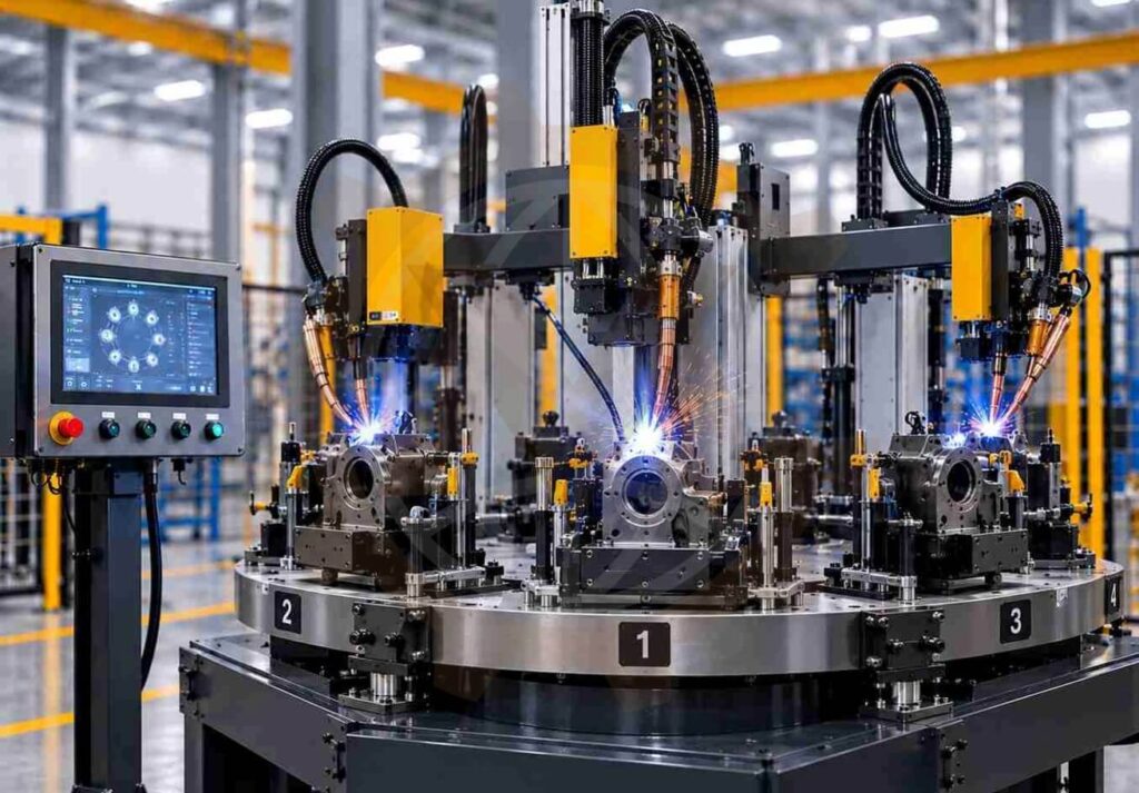
An indexing layout moves workpieces between defined process positions. Depending on the project, these may include loading, fit-up, welding and unloading.
Our mechanical scope can include the indexing-table interface, tooling supports, access openings and surrounding structure. We review index loads, movement envelopes, transfer clearances and the planned sequence with the equipment and controls teams.
Rotary Indexing Welding Stations
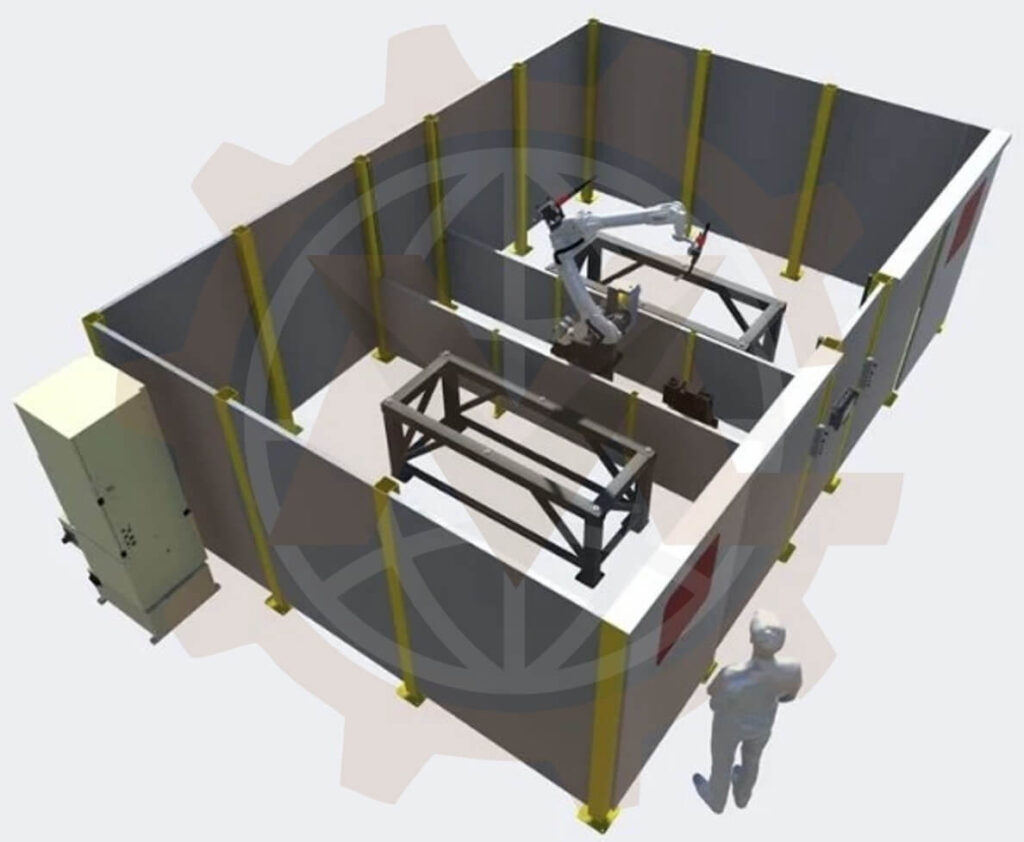
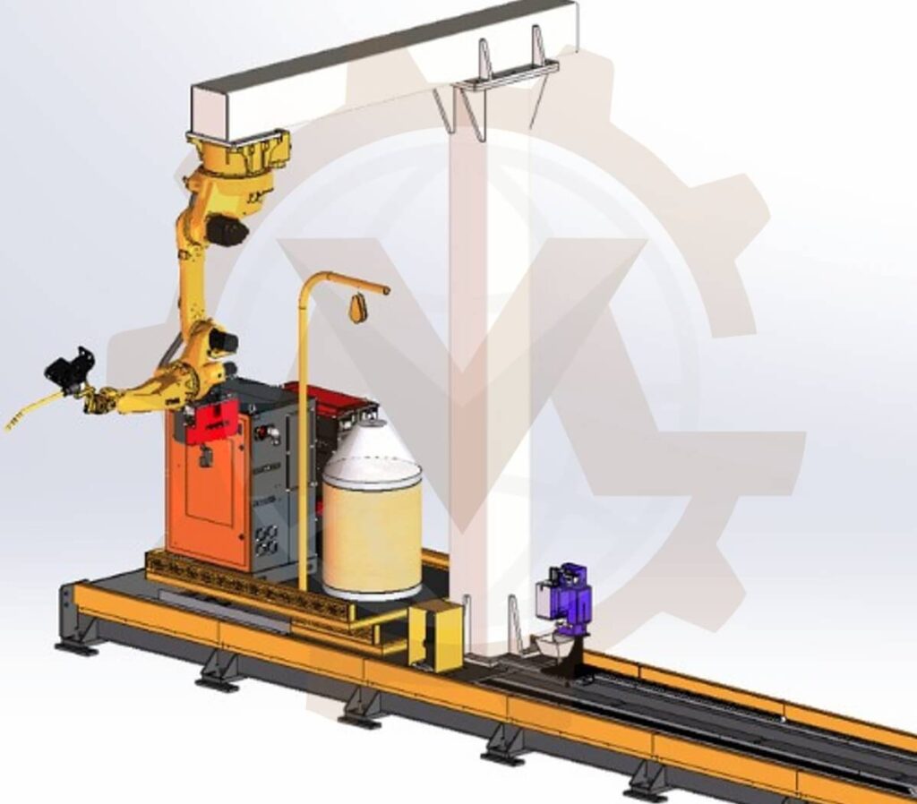
Robotic Welding Station Mechanical Design
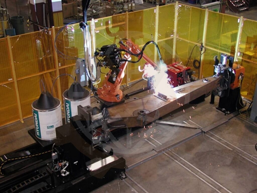
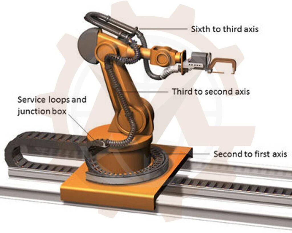
We develop the mechanical arrangement around a selected welding robot, including the base, workholding, positioner interfaces and loading areas. The review considers geometric reach, torch access and nearby equipment.
Robot programming, detailed path simulation and final welding-process validation are separate activities unless agreed in the scope. For projects requiring broader robotic cell development, we coordinate the station with the complete cell layout.
We develop mechanical layouts for booth structures, welding screens and access arrangements, coordinated with the process and site requirements. Material choice, viewing provisions and enclosure openings are reviewed with the relevant specialists.
A welding screen controls exposure to arc light; it does not remove welding fume. Extraction interfaces are addressed separately so the booth and workstation layout can accommodate the selected fume-control approach.
Welding Booth and Screen Layouts
Existing Station Upgrades
We review existing stations where product access, handling, fixture changes or maintenance requirements have evolved. The scope can include a revised layout, additional supports, positioner integration or a new loading arrangement.
The review uses available drawings, site dimensions and production feedback. Reused equipment and structures are assessed against the revised requirements before they become part of the design basis.
Engineering Considerations for a Practical Welding Station
Product Flow and Part Presentation
We review how incoming components are presented, the order in which they are loaded and where finished assemblies are placed. Part racks and transfer positions should support the intended sequence without obstructing the operator or equipment.
For larger assemblies, lifting and transfer methods affect station dimensions. The handling concept is established early rather than added after the fixture is complete.
Operator Access and Ergonomics
We consider working height, loading reach, clamp access and the postures required to reach weld joints. Representative users, protective equipment and task variation inform the layout.
Adjustable equipment or a positioner may help where product geometry creates difficult working positions. There is no single workstation height that suits every welding task; the design is based on the actual operation.
Fixture and Workholding Interfaces
Fixtures must fit the station mechanically and operationally. We coordinate mounting references, clamp sweep, utility connections and the route for removing the completed weldment.
Detailed fixture engineering can be included or supplied by your tooling team. Where only an interface is in scope, the required fixture data and responsibilities are recorded before detailed station design.
Fixture and Workholding Interfaces
Structural Stiffness and Mechanical Loads
Station structures may support heavy products, offset fixtures or moving equipment. We review the relevant load paths and mounting arrangements, including reactions from clamps, acceleration or indexing where applicable.
Calculations or structural assessment are scoped around the actual loads and permitted movement. Floor anchorage and foundation responsibility are defined with the client or site engineer.
Positioning and Movement Clearances
Movement checks consider the product and fixture together, not just the empty mechanism. We review the swept volume of clamps, rotary equipment and moving supports, including loading and maintenance positions.
A clear sequence helps identify when access is permitted and where equipment must be stationary before an operator enters the relevant area. Detailed control and protective functions are coordinated with the integration team.
Fume Extraction Integration
The layout should accommodate the selected welding fume-control system and allow its capture elements to reach the relevant working area. Mechanical scope may include mounting brackets, hood interfaces, space reservations and access for servicing.
Extraction performance depends on the process, capture arrangement and system design. Airflow sizing, filtration selection, exposure assessment and commissioning are defined with a competent ventilation specialist. The arrangement must also be coordinated with welding shielding-gas requirements where relevant.
Arc Screening and Mechanical Guarding
Arc-light screening, moving-machine guarding and fume extraction perform different functions. The station concept must coordinate these elements while preserving suitable access for loading and servicing.
Required protective measures are established through the applicable risk assessment and project requirements. A CAD layout alone is not proof of a complete or validated protective system.
Arc Screening and Mechanical Guarding
Cable Hose and Utility Routing
We plan routing space for welding leads, pneumatic lines and relevant process utilities. The design considers movement, bend requirements, abrasion and exposure to spatter.
Utility connection points should remain accessible. Welding current-return arrangements are coordinated with the process and electrical specialists, including interfaces with positioners and sensitive mechanical components.
Cable Hose and Utility Routing
Maintenance and Product Changeover
Routine tasks such as cleaning, replacing wear parts and accessing torch equipment should be considered in the initial layout. We review whether components can be reached and removed without dismantling unrelated equipment.
For multiple product variants, we can incorporate removable tooling, common mounting references and defined changeover clearances. The changeover method is selected around production frequency and the required setup verification.
Choosing the Right Welding Station Configuration
A manual workstation can be suitable where product variation is high or production volumes do not justify powered functions. Semi-automatic equipment may be useful when repeated clamping or positioning occupies a meaningful part of the cycle. A robot-based solution requires suitable joint access, repeatable inputs and a viable process concept.
We compare configuration options against the product family, expected demand, labor content, available space, changeover needs and investment constraints.
The comparison should include the whole cycle: component preparation, loading, clamping, welding, any required hold time, release and unloading. Reducing weld time alone may not increase output if handling remains the bottleneck.
Where estimates are needed, we separate calculated or assumed task durations from times verified during trials. Quoted production performance is based on the agreed validation method.
Typical Welding Station Applications
Fabricated Frames and Equipment Supports
Workstations for repeated frame and support assemblies, with layouts coordinated around product handling and access to the specified joints.
Sheet Metal Products and Enclosures
Stations for panels, brackets and formed assemblies, taking account of thin-part support, fixture access and product removal.
Tube and Profile Assemblies
Arrangements for tubular or structural-profile products, potentially using rotation or tilting to present weld joints.
Tube and Profile Assemblies
Repeated Industrial Subassemblies
Dedicated or adaptable stations for recurring welded components used in machinery and manufacturing systems.
We review the mechanical requirements around the client’s selected process, including MIG/MAG, TIG or other welding equipment where applicable. Welding procedures, parameters and qualification remain with the agreed welding specialist unless separately included.
We review the product CAD, weld locations, component conditions, existing equipment and production targets. Site dimensions and utility constraints establish the available operating space.
2 Compare Workstation Concepts
Concept layouts establish product flow, operator tasks, equipment placement and the proposed positioning arrangement. We compare the practical implications before selecting a concept for detailed work.
3 Develop the Mechanical CAD Assembly
We model the structure, fixture interfaces, purchased equipment and handling arrangements in Autodesk Inventor. Surrounding access and service envelopes are represented at the agreed level of detail.
Develop the Mechanical CAD Assembly
4 Review Interfaces and Design Checks
The review may include structural loads, positioner capacity, moving envelopes, access and sequence feasibility. We coordinate unresolved process, extraction, controls and site interfaces with the responsible teams.
5 Release Manufacturing Documentation
The approved mechanical design is converted into part drawings, assembly drawings, a general arrangement and a BOM. Critical interfaces and installation dimensions are identified as required.
6 Support Fabrication and Trial Feedback
Agreed support can continue through fabrication, assembly and initial trials. Changes are assessed against the approved requirements and documented through the project revision process.
Welding Station Design Deliverables
The scope can include:
Deliverable
Typical contents
Station layout
Equipment positions, footprint and operating areas
General arrangement drawing
Overall dimensions and relevant access envelopes
3D CAD assembly
Structures, fixture interfaces and selected equipment
Manufacturing drawings
Custom plates, frames, brackets and mechanical details
Assembly drawings
Installation arrangement and component references
Bill of Materials
Manufactured parts, purchased components and quantities
Interface documentation
Mountings, utility provisions and equipment connections
Sequence description
Intended mechanical operations for controls coordination
Review records
Agreed calculations, access checks and design comments
Exchange files
STEP, PDF, DWG or DXF according to scope
Native software version, file structure, revision arrangements and ownership are established in the agreement. Electrical design, PLC programming, robot programming, ventilation-system engineering, physical supply and commissioning are included only where expressly agreed.
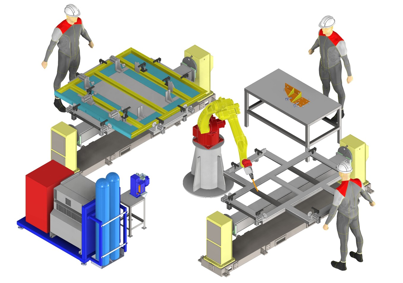
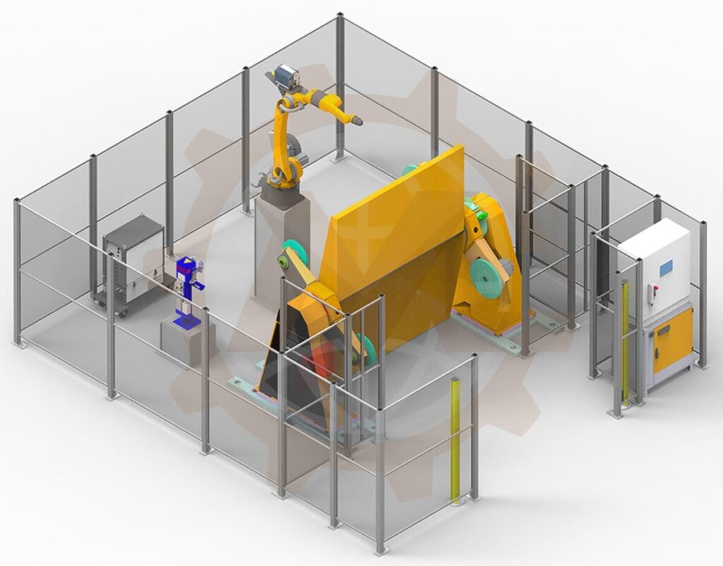
GMD’s semi-automatic robotic welding station case study presents a metal-frame welding application involving custom workholding, pneumatic clamping and rotary positioning equipment.
The project provides an example of the relationship between the fixture, product positioning and station layout.
We consider fabrication, purchased components, assembly access and service requirements while developing the CAD model and drawings.
Coordinated Equipment Interfaces
Our mechanical engineering scope can connect the station structure with fixtures, positioners and handling equipment, giving the integration team a clear set of interfaces to review.
Defined Inputs and Review Stages
We establish deliverables, responsibilities and acceptance requirements before detailed work. Design reviews allow your production and integration teams to assess the evolving layout.
Remote Collaboration and Confidentiality
We work through CAD exchanges, drawing reviews and documented feedback. Client product data is handled under the agreed confidentiality and access arrangements.
Please send the information available for your project:
Component and welded-assembly CAD files.
Weld drawings, critical dimensions and product variants.
Materials, thicknesses and product weights.
Expected production volume and target cycle time.
Proposed manual, semi-automatic or robot-based process.
Existing welding equipment, fixtures and positioners.
Available space, site dimensions and handling constraints.
Extraction-system information and utility interfaces.
Required outputs, CAD version and project schedule.
If the production concept is still developing, we can define an initial layout study before committing to the complete detail-design package.
Frequently Asked Questions
What is the difference between a welding station and a welding fixture?
The fixture locates and holds the workpiece. The station also includes the surrounding structure, equipment placement, operator workflow and handling interfaces. A fixture may be one part of the station design.
Can you design a manual welding station?
Yes. We can develop the bench or base, tooling interfaces, layout and handling arrangements around your product and operator tasks.
Can you design semi-automatic welding stations?
Yes. Mechanical scope can include powered clamps, positioners, indexing and transfer functions. The sequence is coordinated with the responsible controls team.
Can you integrate an existing positioner?
Yes, subject to interface and capacity review. Please provide mounting drawings, ratings and information about the proposed fixture and workpiece.
Can a dual-station layout allow loading during welding?
It may, where the process and protective concept permit concurrent operation. We review physical separation and equipment movement with the integration team; the final system requires the appropriate validation.
Do you provide welding booth design?
Mechanical scope can include booth structures, screen supports and access layouts. Extraction and protective-system requirements are coordinated with the relevant specialists.
Do you design the fume extraction system?
We can incorporate the agreed mechanical interfaces and space provisions. Airflow design, filtration and extraction-performance validation are separately scoped with a competent specialist.
Do you provide robot programming?
This service primarily covers mechanical station engineering. Robot programming and detailed path simulation are separately agreed or performed by the client’s integrator.
Can you improve an existing welding workstation?
Yes. We review its layout, equipment interfaces and reported production issues, then propose changes based on verified dimensions and requirements.
Can one welding station support several products?
It can where geometry, process and production needs allow. Adjustable layouts or interchangeable tooling may support variants, with defined changeover and setup checks.
Do you provide 3D CAD drawings and a BOM?
Yes, according to the project scope. The package can include native CAD, manufacturing and assembly drawings, GA drawings, a BOM and neutral file formats.
What affects the cost of welding station design?
Cost depends on layout complexity, automation, product variation, equipment interfaces, analysis and documentation requirements. Representative CAD and a process brief help us prepare a suitable proposal.
Need a welding station that brings your tooling, handling and production workflow together?
Share your product drawings, current process or proposed layout with GMD Engineering. We will help define a practical mechanical design scope for a new station or an upgrade to existing equipment.
We use cookies to make our website work, analyse traffic and improve your experience. You can accept all cookies, deny non-essential cookies or manage your preferences. You can change your choice at any time. For more information, please see our Cookie Policy.
Functional
Always active
The technical storage or access is strictly necessary for the legitimate purpose of enabling the use of a specific service explicitly requested by the subscriber or user, or for the sole purpose of carrying out the transmission of a communication over an electronic communications network.
Preferences
The technical storage or access is necessary for the legitimate purpose of storing preferences that are not requested by the subscriber or user.
Statistics
The technical storage or access that is used exclusively for statistical purposes.The technical storage or access that is used exclusively for anonymous statistical purposes. Without a subpoena, voluntary compliance on the part of your Internet Service Provider, or additional records from a third party, information stored or retrieved for this purpose alone cannot usually be used to identify you.
Marketing
The technical storage or access is required to create user profiles to send advertising, or to track the user on a website or across several websites for similar marketing purposes.