Robotic Vision Inspection System for Cast Parts
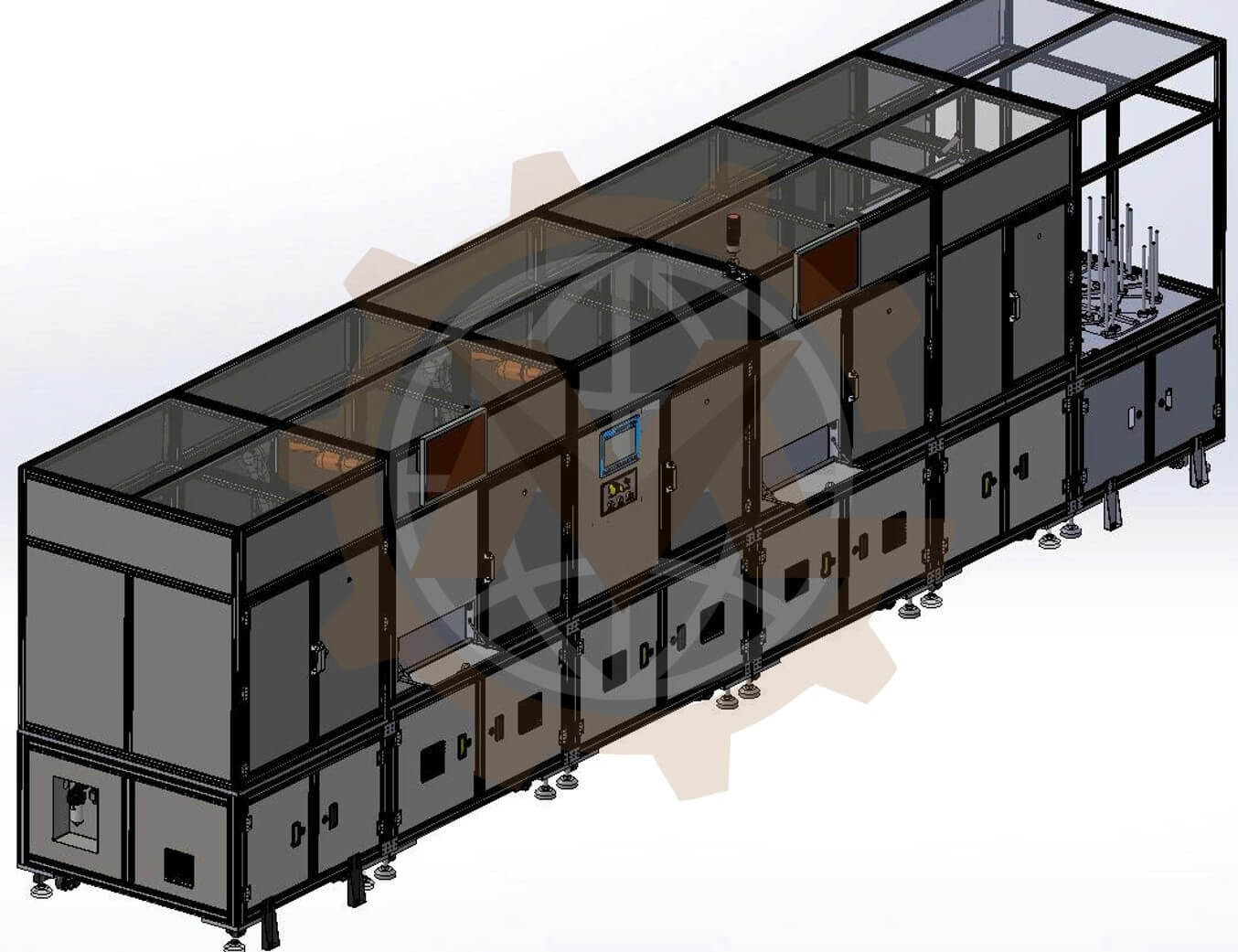
GMD designed an automated visual inspection system for cast parts. The line separates parts from incoming stacks, presents both sides to robot mounted vision systems, checks height with a 3D camera, removes rejected parts and restacks accepted products
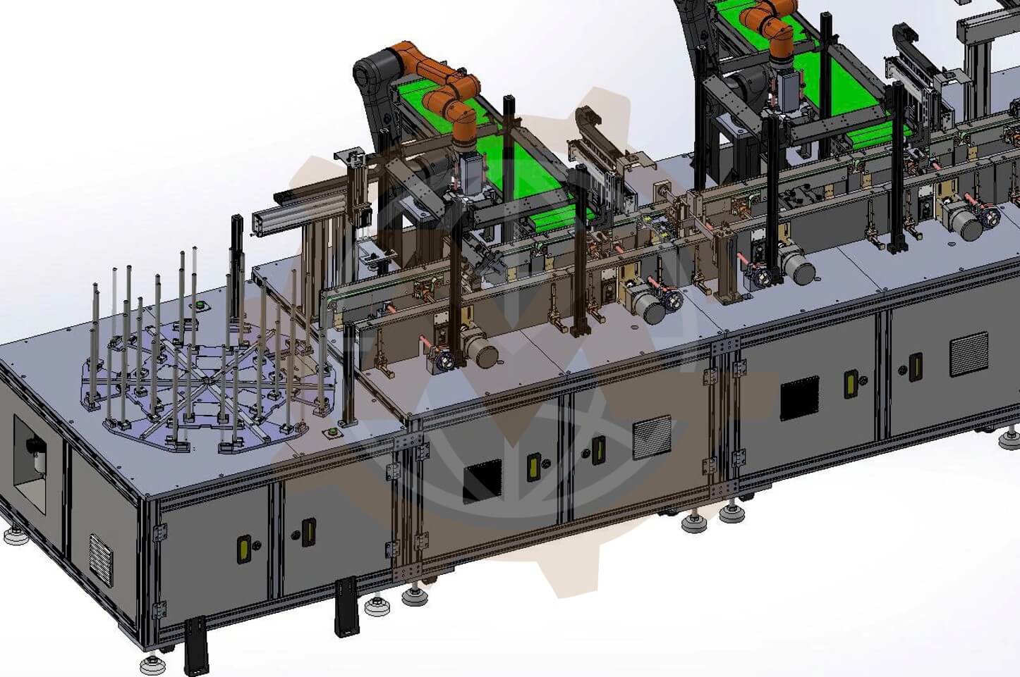
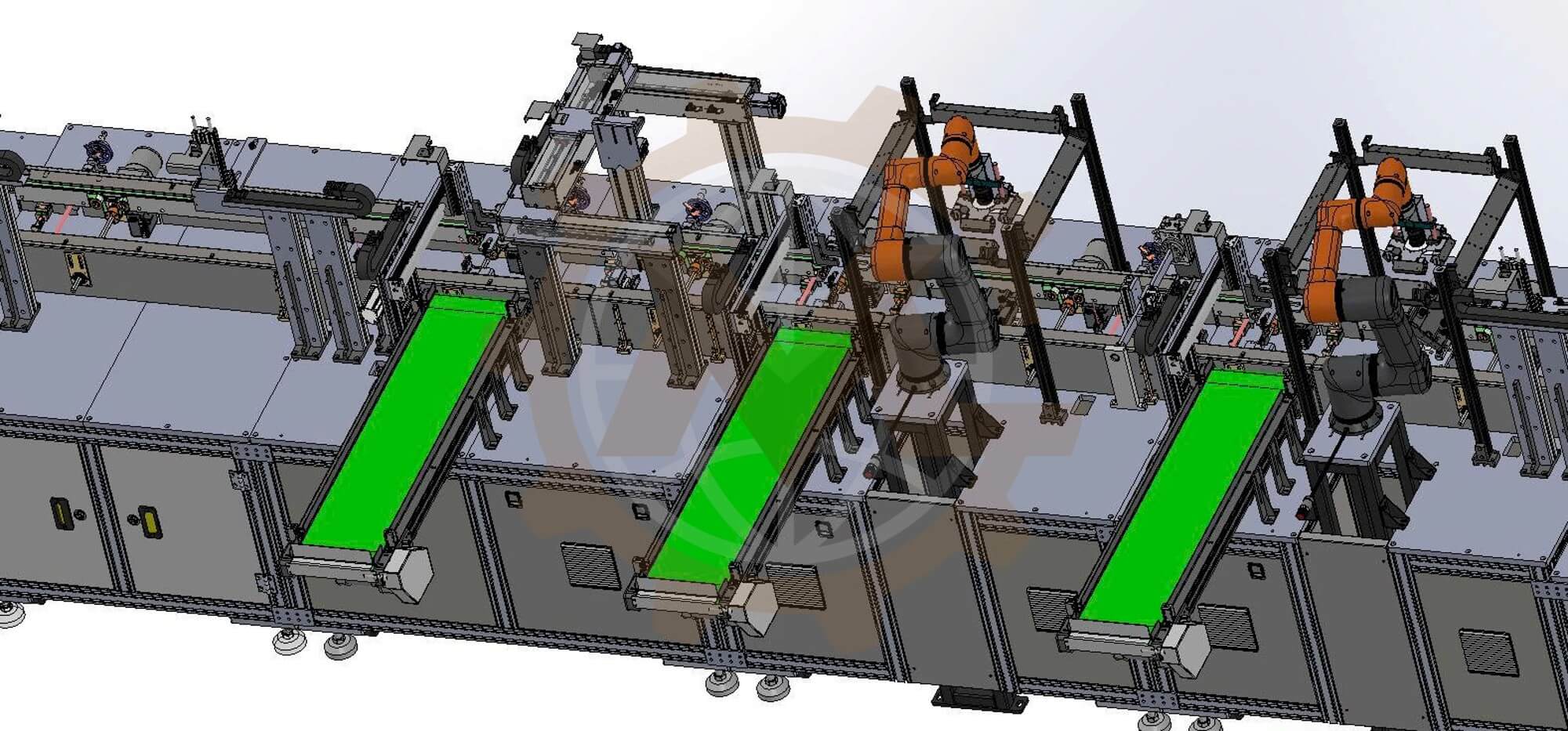
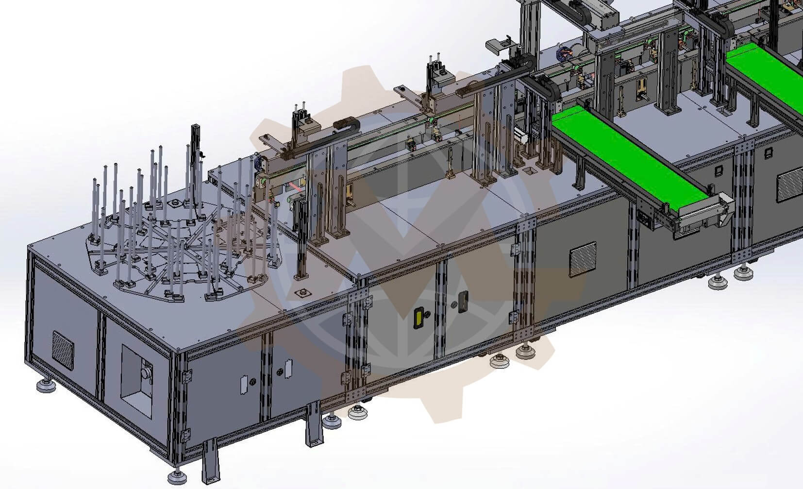
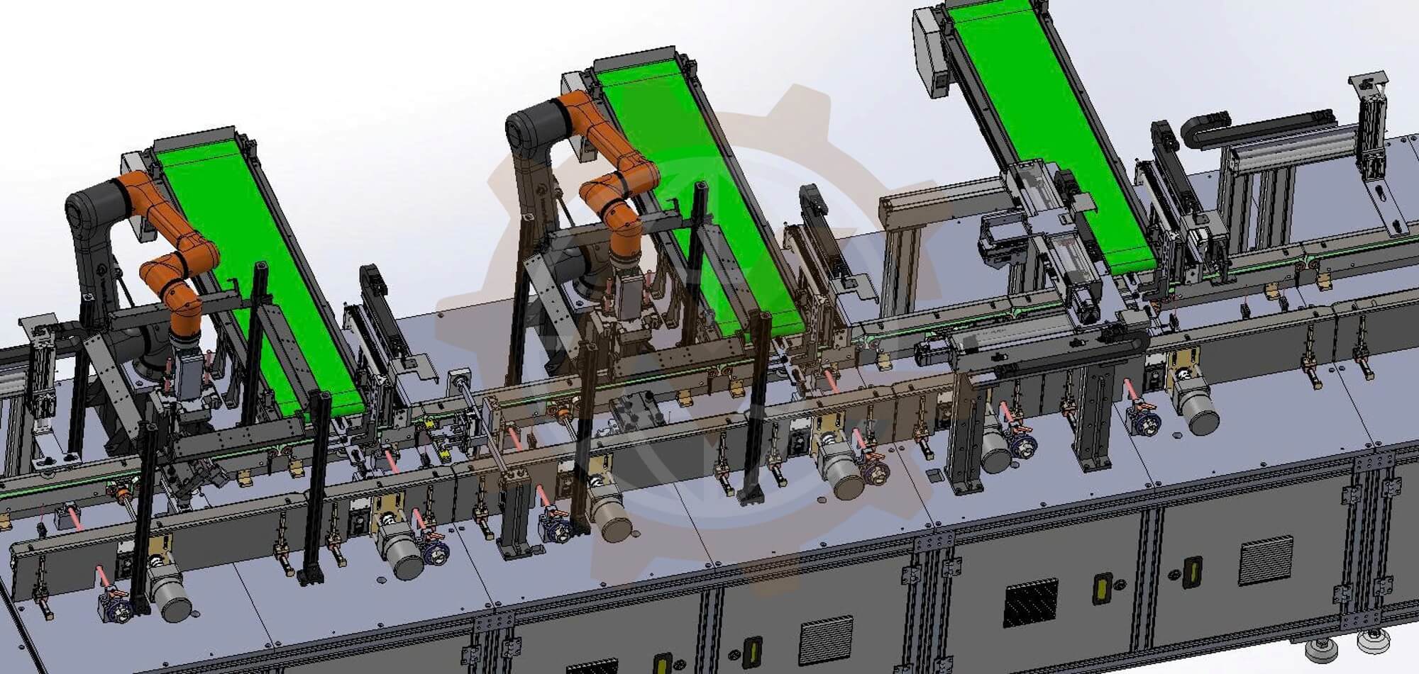
Cast parts can have defects in areas that are difficult to inspect from a fixed camera position. Edges, ribs, recessed features and the opposite face of a part may each require a different viewing angle. An automated inspection line must therefore control both how the part is presented and where the camera moves.
GMD designed a system that separates cast parts from incoming stacks, conveys them through two visual inspection stages, turns them over for inspection of the opposite face and performs a final 3D height check. Parts classified as nonconforming are removed at the relevant stage. Accepted parts are assembled into outgoing stacks for operator collection.
1. Cast Part Production and Inspection Context
The project concerns a cast component with multiple raised features, recesses, mounting points and perimeter edges. These geometric details create several areas where casting defects may need to be checked.
The inspection process was designed to assess specified features such as overall shape, selected dimensional criteria, burrs, surface porosity and visible cracks. Inspection criteria and acceptable limits are defined for the product being processed.
2. Inspecting Complex Geometry From Both Sides
A single overhead image cannot provide a clear view of every relevant feature on this part. The system needed to expose different faces and edges to the cameras while keeping the part in a known position.
It also had to move parts reliably between stations, remove rejected products without sending them through the full line, and restack accepted parts at the output. These operations had to work together as one controlled sequence.
3. Product Handling and Inspection Requirements
The design requirements covered the complete path from stacked input to stacked output:
- Accept stacks of cast parts loaded by an operator.
- Separate and feed individual parts onto the main conveyor.
- Present each part to a vision system at multiple viewing angles.
- Turn accepted parts over to expose the opposite face.
- Repeat visual inspection on the second side.
- Use a 3D camera to check the specified product height criteria.
- Remove nonconforming parts after the applicable inspection stage.
- Restack accepted parts to the required stack quantity.
- Return completed stacks to an operator access position.
4. Positioning Constraints for Reliable Vision Checks
Vision inspection depends on repeatable part presentation. The handling mechanisms needed to pick up and place the casting consistently so that the programmed camera positions corresponded to the intended features.
At each main inspection station, a vacuum handling mechanism tilts the part approximately 45 degrees and rotates it through 360 degrees. This movement exposes the perimeter and additional surfaces while a six axis robot positions the vision system at the required viewpoints.
After the first inspection, a turnover mechanism rotates accepted parts 180 degrees. The second inspection station can then examine the opposite face. The sequence also required space for separate rejection points and an independent 3D height check before final stacking.
5. Inspection Concepts Considered
| Inspection approach | Design consideration |
|---|---|
| Fixed camera above the conveyor | Limited access to side faces, recesses and the opposite face |
| Multiple fixed cameras around the product | Requires several camera positions and careful coordination around the part |
| Robot mounted vision with controlled part rotation | Allows the camera viewpoint and part orientation to change according to the inspection sequence |
The selected system combines robot mounted vision with controlled tilting, rotation and turnover of the part. A separate 3D camera station addresses the specified height check.
6. Selected Mechanism and Operating Sequence
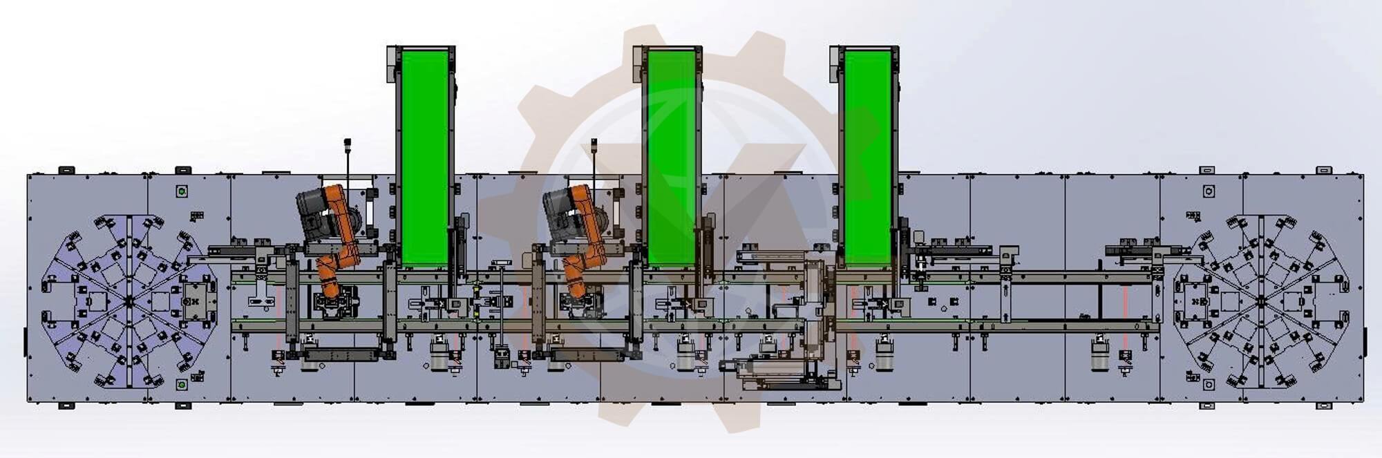
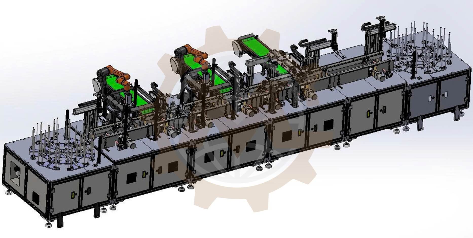
An operator loads a stack of cast parts onto an indexing rotary table. The table presents the stack to a step lift, which raises it incrementally as individual parts are removed. A pick and place unit transfers each part to the main conveyor.
At the first vision station, a vacuum mechanism lifts and tilts the part. The part rotates through a full revolution while a six axis robot moves the vision system to inspect programmed features from several angles. The mechanism then returns the part to the conveyor. A part classified as nonconforming is removed from the line.
An accepted part proceeds to a turnover unit, which rotates it 180 degrees and places it back on the conveyor. A second tilt and rotation station presents the opposite face for another robot guided visual inspection. Parts rejected at this stage are removed to a separate reject conveyor.
Parts that pass both visual checks move to a 3D camera station for the defined height inspection. A subsequent reject station removes parts that fail this check.
Finally, a pick and place unit transfers accepted parts to an output stacker. Its step lift moves downward as parts are added, maintaining the receiving position. Once the required stack quantity is reached, the rotary output table presents the completed stack for operator removal.
7. Engineering Checks Behind the Inspection Sequence
The mechanical and process design required coordination of several movements:
- Step lift travel: the change in stack height as each part is removed or added.
- Pickup position: repeatable access to the top part of the incoming stack and the top of the outgoing stack.
- Vacuum handling: sufficient holding capacity throughout lifting, tilting and rotation.
- Rotation clearance: space for the casting to complete a 360 degree turn without contacting nearby equipment.
- Turnover clearance: room to rotate the part 180 degrees and return it to the conveyor.
- Robot reach: access to the required inspection viewpoints on both faces.
- Conveyor and station timing: transfer of parts without overlapping movements at adjacent stations.
- Inspection repeatability: consistent part positioning and validated camera setup for each defined check.
The inspection tolerances, cycle time, detection performance and throughput are not stated here because verified project values were not provided.
8. CAD Model and Vision System Integration
The 3D design brings the input and output rotary tables, step lifts, conveyor, pick and place units, tilt and rotation mechanisms, turnover station, robot inspection areas, 3D camera station and reject conveyors into one layout.
The CAD assembly allows the team to assess part movement, mechanical clearances, robot access and equipment interfaces before fabrication. Vision recipes and dimensional acceptance limits must be configured and validated against representative good and defective parts during system integration.
9. Engineering Deliverables
The project design covers the integrated inspection line and its principal handling mechanisms:
- Stack loading and singulation arrangement.
- Main conveyor and part transfer units.
- Two tilt and rotation inspection stations.
- Part turnover mechanism.
- Robot and vision equipment mounting interfaces.
- 3D height inspection station.
- Reject handling at the applicable inspection stages.
- Accepted part stacking and operator collection arrangement.
The final list of drawings, BOMs, controls programs and vision software files should follow the actual contracted delivery scope.
10. Inspection Coverage Across Both Faces and Final Height
The designed sequence provides two robot guided visual inspection stages, with a 180 degree turnover between them, followed by a 3D height check. Each visual stage can present the part at a 45 degree tilt and rotate it through 360 degrees for the programmed viewpoints.
The line also provides separate removal points for nonconforming parts and automatically restacks accepted products. These describe the system’s design functions; production rate and inspection accuracy should be published only after validation.
11. Related Engineering Services
This project combines custom machine design, automated part handling, conveyor integration and robotic inspection station design. Similar solutions can be developed for castings, molded parts and other components that require inspection of multiple faces and geometric features.
12. Need an Automated Inspection System for Your Parts?
GMD can help turn your inspection requirements into a mechanical handling concept and integrated equipment layout. Share the part model, defect criteria, acceptable tolerances, target cycle time and examples of good and defective parts to begin the engineering review.