
Automatic Dual-Head Pad Printing Machine Design
GMD Engineering developed an automatic dual-head pad printing machine featuring two independent printing units arranged around a central rotary indexing table. Custom fixtures maintain accurate product positioning while the synchronized printing stations apply two patterns or colors with improved repeatability and production efficiency.
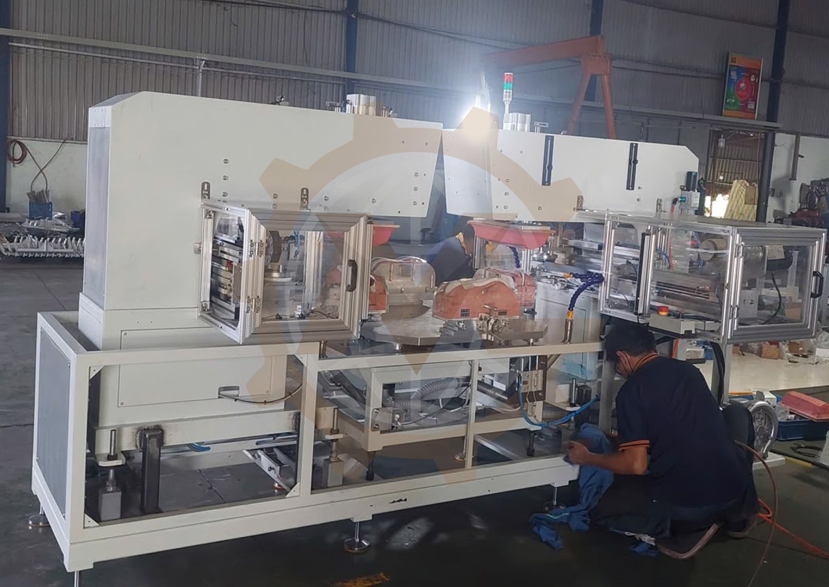
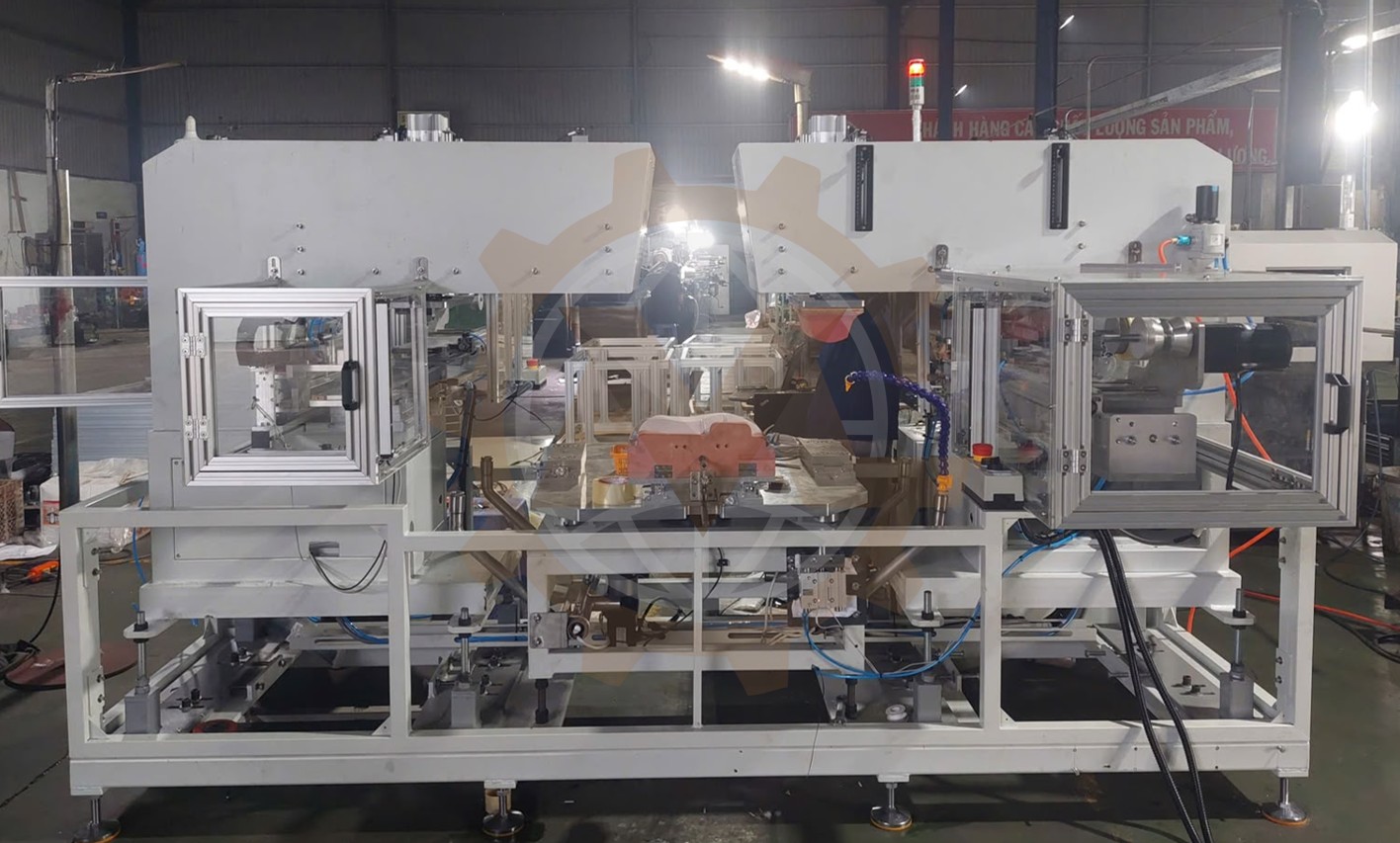
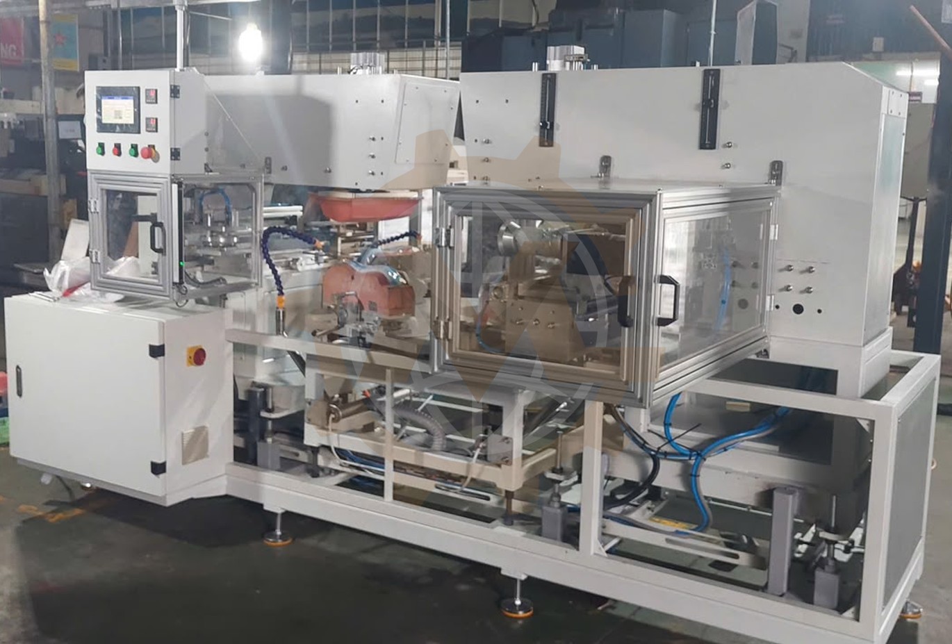


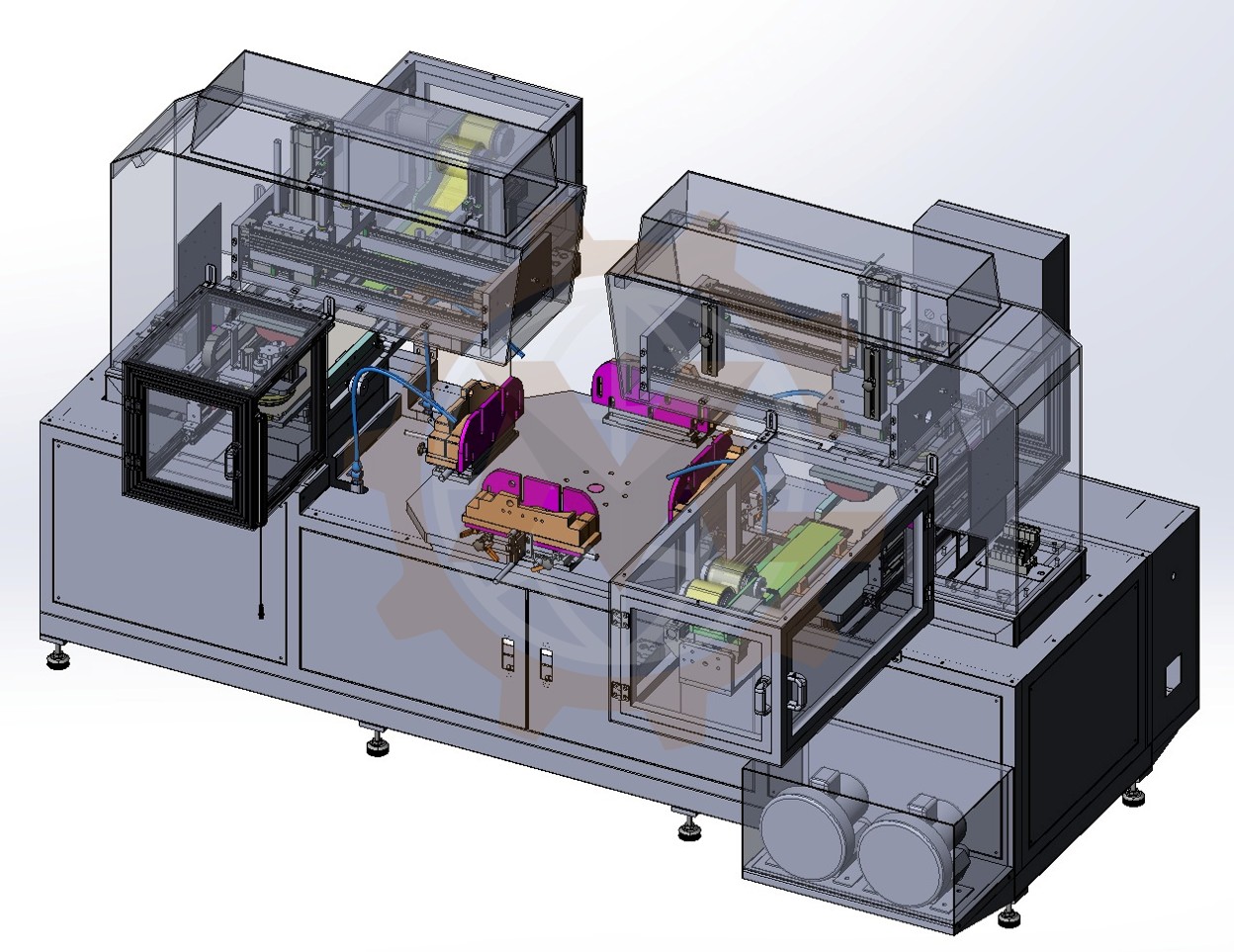

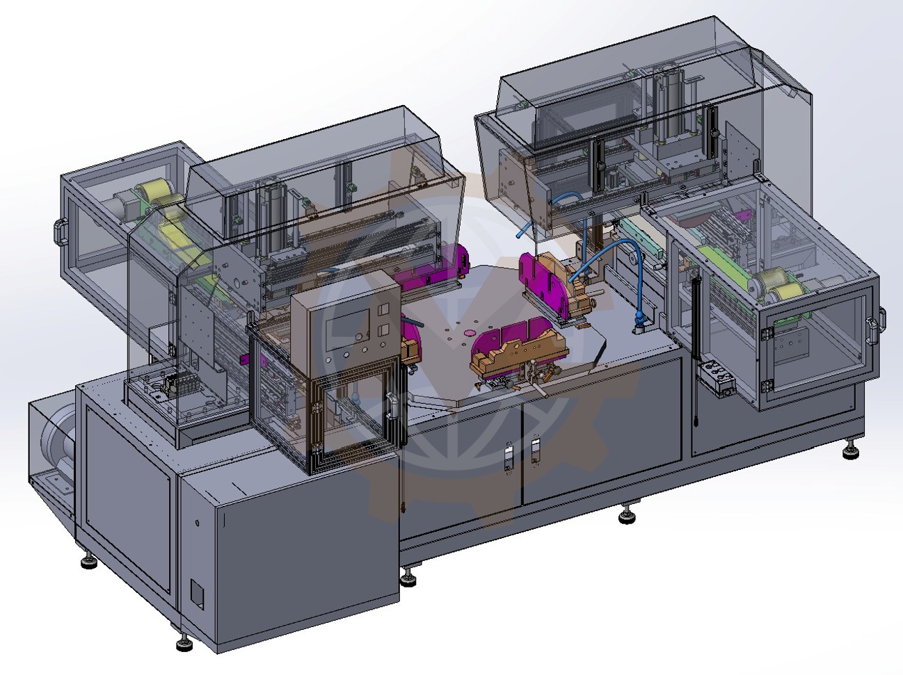
GMD Engineering developed an automatic dual-head pad printing machine designed to apply two printing patterns or colors to products positioned on a central rotary indexing table. The machine incorporates two independent pad printing units arranged around the same rotary table, allowing products to move sequentially through both printing stations.
Each product is securely held in a dedicated fixture to maintain accurate positioning throughout the printing process. The rotary indexing system transfers the product from the loading station to the first printing head, then to the second printing head, and finally to the unloading position.
This configuration provides a compact and efficient solution for products requiring multiple printed areas, colors, or printing operations within the same automated cycle.
Dual-Station Pad Printing System Configuration
The machine was developed around a central rotary indexing table with multiple product fixtures. Two pad printing heads are installed at separate working positions around the table.
The first printing unit performs the initial printing operation. After the rotary table advances by one indexed position, the second unit applies the next pattern, color, or printing layer.
The complete system integrates:
- Two independent pad printing units.
- A central rotary indexing table.
- Custom product positioning fixtures.
- Pneumatic printing and ink-transfer mechanisms.
- Product loading and unloading positions.
- Accurate mechanical indexing.
- PLC-based sequence control.
- Operator control panel and HMI.
- Safety guarding around the moving components.
- Machine frame and equipment enclosure.
The layout allows both printing heads to operate during the same machine cycle. While one product is being printed at the first station, another product can be processed at the second station.
Multi-Stage Printing Process Requirements
The main objective of this project was to develop a machine capable of producing consistent printed patterns on products with complex or curved surfaces.
The system needed to:
- Hold each product in a repeatable printing position.
- Apply two separate printing operations.
- Maintain registration between the two printed patterns.
- Allow the two printing units to work simultaneously.
- Automatically index products between stations.
- Minimize manual product handling.
- Improve printing consistency and repeatability.
- Reduce waiting time between printing operations.
- Allow convenient replacement of printing plates, pads, and fixtures.
- Protect operators from moving machine components.
The machine also needed to provide sufficient adjustment for setting the printing position, pad stroke, transfer pressure, and product fixture location.
How the Dual-Head Pad Printing Machine Works
1. Product Loading onto the Rotary Table
The operator places the product into a dedicated fixture at the loading position of the rotary table.
The fixture supports the product according to its shape and establishes consistent reference surfaces. Locating pins, side supports, stops, or clamping components can be used to ensure that every product enters the machine in the same position.
A product presence sensor can confirm that the product has been loaded correctly before the rotary table is allowed to move.
2. Rotary Table Indexing
After the product is loaded and the required safety conditions are confirmed, the rotary table advances by one indexed position.
The table moves the product from the loading area to the first pad printing station. At the same time, other products already on the table move to their next respective stations.
The indexing mechanism ensures that each fixture stops at a repeatable angular position beneath the corresponding printing head.
3. First Pad Printing Operation
At the first printing station, the initial printing head transfers the required image from the printing plate onto the product surface.
The pad printing process typically follows these steps:
- Ink fills the engraved pattern on the printing plate.
- The ink cup or doctoring mechanism removes excess ink.
- The silicone pad moves downward onto the engraved image.
- The pad picks up the ink pattern.
- The pad moves toward the product.
- The pad presses against the product surface.
- The ink pattern is transferred onto the product.
- The pad returns to its starting position.
The flexible silicone pad conforms to curved or irregular product geometry, making pad printing suitable for components that cannot be printed effectively using a flat printing method.
4. Transfer to the Second Printing Station
When the first printing operation has been completed, the printing head returns to its safe position.
The rotary table then advances the product to the second pad printing unit. Mechanical indexing and fixture accuracy help maintain the required relationship between the first and second printed patterns.
This repeatable transfer is particularly important when the two printing operations create a combined image or apply two different colors to closely positioned areas.
5. Second Pad Printing Operation
The second printing unit performs the next required printing operation.
Depending on the product requirements, this station may:
- Apply a second color.
- Print an additional graphic.
- Add text, a logo, or identification information.
- Print another section of the product.
- Complete a multi-layer image.
- Apply a pattern from a different direction.
Because the two printing heads are independent, their printing plates, ink colors, silicone pads, stroke settings, and operating parameters can be configured separately.
6. Simultaneous Dual-Station Operation
The two pad printing units can operate simultaneously on separate products positioned at their respective stations.
During the same machine cycle:
- The first printing head applies the initial pattern to one product.
- The second printing head completes the next pattern on another product.
- The operator can load or unload a product at an accessible station, depending on the table configuration.
Parallel operation significantly improves productivity compared with a process where one printing head performs all operations sequentially on a single product.
7. Finished Product Unloading
After both printing operations have been completed, the rotary table moves the finished product to the unloading position.
The product can be removed manually by the operator or automatically transferred to an outfeed conveyor or downstream process if a higher automation level is required.
The empty fixture then returns to the loading station and becomes available for the next product.
Main Mechanical Assemblies
Central Rotary Indexing Table
The rotary table is the central product-transfer mechanism of the machine. It carries multiple fixtures and moves products sequentially through the printing process.
The table assembly is designed to provide:
- Accurate angular indexing.
- Sufficient rigidity during printing.
- Repeatable fixture positioning.
- Smooth acceleration and deceleration.
- Suitable load capacity for the products and tooling.
- Easy access for fixture replacement and maintenance.
The number of table positions can be selected according to the required loading, printing, inspection, drying, and unloading operations.
Two Independent Pad Printing Units
Two pad printing assemblies are positioned around the rotary table. Each unit contains the mechanisms required to collect ink from the printing plate and transfer the pattern to the product.
The principal components include:
- Printing plate or cliché.
- Closed ink cup or ink distribution system.
- Silicone printing pad.
- Horizontal transfer mechanism.
- Vertical pad movement mechanism.
- Pad support and adjustment structure.
- Printing force and stroke adjustment.
- Printing unit frame and protective enclosure.
Independent adjustment allows each unit to be aligned according to its specific printing area.
Custom Product Fixtures
Dedicated fixtures hold the products on the rotary table. Their geometry is developed according to the product shape, material, printing area, and required orientation.
The fixtures help:
- Prevent product movement during printing.
- Maintain consistent printing registration.
- Support the product against pad pressure.
- Protect sensitive product surfaces.
- Reduce operator loading errors.
- Improve changeover repeatability.
Replaceable tooling can be provided when the machine needs to process multiple product variants.
Printing Head Adjustment Mechanisms
Pad printing quality depends on accurate alignment between the silicone pad, printing plate, and product.
The printing units can therefore incorporate mechanical adjustments for:
- Horizontal printing position.
- Vertical printing height.
- Pad stroke.
- Printing pressure.
- Printing plate position.
- Product-to-pad alignment.
- Printing angle where required.
These adjustment points simplify initial setup and help compensate for differences between product variants.
Machine Frame and Equipment Enclosure
The machine is built on a rigid structural frame that supports the rotary table, printing stations, pneumatic equipment, electrical cabinet, and guarding.
The enclosed lower frame provides space for:
- Rotary indexing drive components.
- Pneumatic valves and regulators.
- Electrical wiring.
- Machine control components.
- Cable routing.
- Maintenance access.
Adjustable leveling feet support accurate machine installation on the factory floor.
Safety Guarding System
Transparent safety panels surround the printing stations and rotary mechanisms while allowing the operator to observe the process.
Access doors can be equipped with safety interlock switches. If a protected door is opened during automatic operation, hazardous movement is stopped according to the designed safety sequence.
Automation and Operating Sequence
The printing process can be controlled by a PLC and monitored through an HMI.
A typical automatic cycle includes:
- The operator loads a product into the available fixture.
- A sensor confirms product presence.
- The machine verifies that both printing heads are in their safe positions.
- The rotary table advances by one indexed position.
- The table locks at the required angular position.
- The first printing unit applies the initial pattern.
- The second printing unit simultaneously prints another product.
- Both printing heads return to their starting positions.
- The PLC confirms completion of both printing operations.
- The rotary table advances again.
- The product moves from the first station to the second station.
- The finished product reaches the unloading position.
- The cycle repeats.
The HMI can provide functions such as:
- Automatic and manual operating modes.
- Production quantity display.
- Printing parameter selection.
- Product recipe management.
- Machine cycle monitoring.
- Cylinder and sensor status.
- Alarm messages.
- Maintenance functions.
- Individual mechanism testing.
- Production counter reset.
Key Engineering Challenges
Maintaining Registration Between Two Prints
When two separate printing heads apply patterns to the same product, the relative position between the prints must remain consistent.
Accurate rotary indexing, rigid fixtures, and controlled product location are essential to prevent visible misalignment.
Printing on a Complex Product Surface
Curved or irregular product geometry can create uneven contact between the printing pad and the surface.
The silicone pad shape, hardness, printing force, stroke, and product support must be selected to provide complete ink transfer without deforming or damaging the product.
Synchronizing Two Printing Units
Both printing heads need to complete their operations before the rotary table can move.
The PLC sequence monitors the positions of the horizontal and vertical mechanisms and allows indexing only after both printing units have returned to their safe positions.
Providing Independent Print Adjustment
The two printing operations may require different pad strokes, positions, ink colors, and pressing forces.
Independent mechanical adjustments allow each station to be optimized without affecting the other printing unit.
Controlling Ink and Process Stability
Stable printing quality depends on controlling several variables, including:
- Ink viscosity.
- Ink cup condition.
- Printing plate cleanliness.
- Silicone pad condition.
- Printing pressure.
- Pad contact time.
- Ambient temperature.
- Time between the first and second printing operations.
The machine layout provides access for routine cleaning, ink replacement, pad replacement, and printing plate adjustment.
Machine Safety Features
The machine incorporates several safety measures for the rotary table, printing heads, pneumatic actuators, and operator loading area.
Typical safety features include:
- Transparent perimeter guarding.
- Safety-interlocked access doors.
- Emergency stop push buttons.
- Rotary table position monitoring.
- Pneumatic cylinder position sensors.
- Product presence detection.
- Low air-pressure monitoring.
- Printing head safety interlocks.
- Controlled restart after a machine stop.
- Fault and alarm display on the HMI.
- Stack light for machine status indication.
- Accessible manual controls for setup and maintenance.
The final safety configuration should be confirmed through a formal machine risk assessment and the regulations applicable at the installation location.
Performance and Manufacturing Benefits
The completed dual-head pad printing machine provides several benefits:
- Two printing operations integrated into one machine.
- Simultaneous operation of both printing heads.
- Improved printing position repeatability.
- Consistent registration between printed patterns.
- Reduced manual product transfer.
- Shorter total processing time.
- Increased production capacity.
- Better control of printing quality.
- Compact rotary-table configuration.
- Convenient access for setup and maintenance.
- Flexible tooling for different product variants.
- Potential integration with automatic loading and unloading systems.
Mechanical Design Deliverables
GMD Engineering’s design scope for this project included:
- Machine concept development.
- Complete 3D mechanical design.
- Rotary indexing table integration.
- Dual pad printing station arrangement.
- Product fixture and locating system design.
- Printing head support and adjustment mechanisms.
- Pneumatic actuator integration.
- Machine frame development.
- Safety guarding design.
- HMI and control panel mounting arrangement.
- Cable and pneumatic tube routing.
- Design for manufacturing and assembly.
- Detailed 2D manufacturing drawings.
- General assembly drawings.
- Bill of Materials preparation.
Custom Pad Printing Automation Services
GMD Engineering provides custom machine design and industrial automation engineering services for manufacturers, machine builders, and production companies worldwide.
Our capabilities include:
- Automatic pad printing machine design.
- Multicolor printing automation.
- Rotary indexing machine design.
- Product positioning fixture development.
- Automatic loading and unloading mechanisms.
- Custom assembly machine design.
- Pick-and-place systems.
- Conveyor system design.
- Pneumatic automation.
- Machine frame and safety guarding design.
- 3D CAD modeling.
- 2D manufacturing drawings.
- Bill of Materials development.
- Motion simulation and mechanism verification.
Each machine is developed according to the product geometry, printing locations, number of colors, target cycle time, production capacity, available factory space, and required automation level.
Need a Custom Pad Printing Machine?
If you need to automate pad printing for curved, irregular, or multi-surface products, GMD Engineering can support your project from initial concept development through detailed mechanical design and manufacturing documentation.
Contact us to discuss your product geometry, required print pattern, number of colors, printing locations, production capacity, and target cycle time.
Looking for a Custom Pad Printing Solution?
Contact GMD Engineering to discuss your automatic pad printing, rotary indexing, or custom printing machine project.