Semi-Automatic Robotic Welding Station for Metal Frame Production



Project Overview
GMD Engineering developed a semi-automatic robotic welding station for welding fabricated metal frames with improved consistency, repeatability and production efficiency.
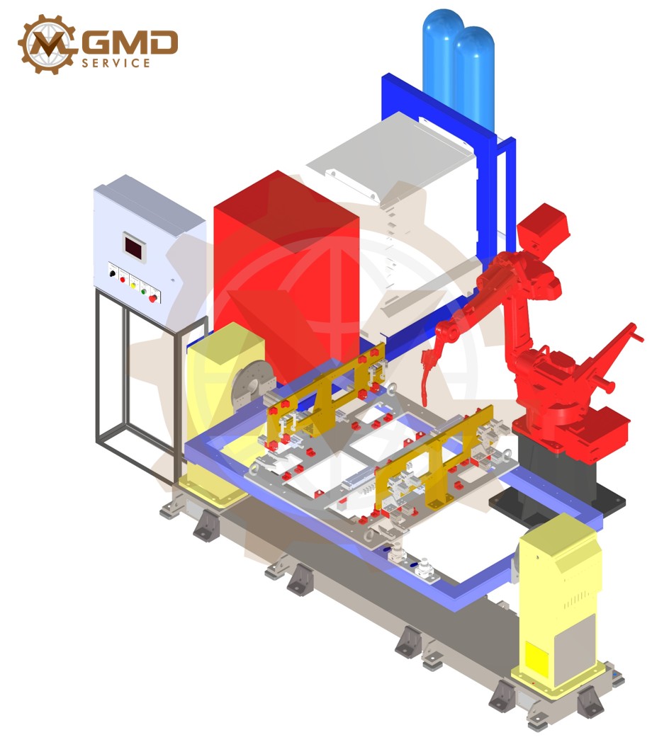
The system combines a robotic welding unit, a custom-designed jig, pneumatic clamping cylinders and a programmable rotary welding positioner. Operators manually load the individual frame components into the fixture and remove the finished assembly, while the clamping, positioning and robotic welding sequences are automated.
This approach provides a practical balance between manual production and full automation. It reduces repetitive welding work while retaining operator flexibility during component loading, inspection and product changeover.
Project Objectives
The primary objective was to create a reliable welding station capable of holding multiple frame components in the correct position throughout the welding process.
The system was designed to:
- Maintain the required position and alignment of the frame components.
- Reduce component movement and deformation during welding.
- Allow the robot to access weld joints from different orientations.
- Improve consistency between finished assemblies.
- Reduce manual welding operations.
- Simplify loading and unloading for the operator.
- Support repeatable production cycles.
- Provide a practical foundation for future production expansion.
Engineering Challenges
Welding a fabricated frame involves more than programming a robot to follow a welding path. Each individual component must be positioned and secured accurately before welding begins.
If the components are not properly located or clamped, several problems may occur:
- Incorrect frame dimensions.
- Misalignment between individual members.
- Gaps between mating components.
- Movement caused by welding forces or heat input.
- Inconsistent weld locations.
- Limited access to weld joints.
- Increased rework and manual correction.
The frame also contains joints located on different sides and orientations. A fixed horizontal fixture would limit robot access and could force the welding robot to operate in less favorable welding positions.
To address these challenges, GMD Engineering integrated the welding jig with a controlled rotary positioner. The positioner rotates the complete fixture and workpiece during the welding cycle, presenting each weld joint to the robot at a suitable angle.
The Engineering Solution
The completed concept consists of four main functional systems:
1. Custom Welding Jig
The welding jig contains dedicated locating surfaces, stops and supports corresponding to the geometry of the frame components.
These locating features help the operator place each part in its intended position before clamping. They also reduce dependence on manual measurement during every production cycle.
The fixture structure is designed to provide sufficient rigidity while maintaining access for loading, unloading and robotic welding.
2. Pneumatic Clamping System
Multiple pneumatic cylinders are installed at selected positions around the fixture.
After all frame components have been loaded, the operator actuates the pneumatic control switch. The cylinders extend and apply clamping force to hold the components against the locating surfaces.
The pneumatic system provides a faster and more repeatable clamping method than using multiple manual clamps. It also ensures that the components remain secured while the fixture rotates and the robot performs the welding sequence.
3. Rotary Welding Positioner
The complete jig is mounted on a powered rotary positioner.
During the automatic cycle, the positioner rotates the workpiece to a series of programmed angles. This enables the welding robot to reach joints located on different sides of the frame while maintaining appropriate torch orientation and welding conditions.
Coordinating the positioner with the welding robot improves accessibility and reduces the need for the robot to reach difficult or unstable positions.
4. Robotic Welding System
The industrial robot follows programmed welding paths for the required joints.
Its motion is coordinated with the rotary positioner so that the frame is presented at the correct orientation for each stage of the welding process. Once all welding operations are completed, the robot returns to its predefined home position.
Operating Process
Step 1: Loading the Frame Components
The operator places the individual metal frame members into the welding jig.
Mechanical stops, locating edges and supporting surfaces guide each component into its intended position. This allows the operator to prepare the assembly without measuring every component manually during each cycle.
Before clamping, the operator verifies that all components are seated correctly against the designated locating features.
Step 2: Pneumatic Clamping
After loading is complete, the operator actuates the pneumatic control switch.
The pneumatic cylinders extend in the specified sequence and press the frame components firmly against the locating surfaces. This secures the assembly and helps maintain its geometry throughout the positioning and welding operations.
The welding cycle should only be permitted after confirmation that the required clamps have reached their working positions.
Step 3: Moving to the Initial Welding Position
Once the clamping sequence has been completed and confirmed, the rotary positioner moves the fixture to the first programmed welding angle.
The rotation places the required joints within the robot’s working envelope and provides a suitable approach angle for the welding torch.
Step 4: Multi-Angle Robotic Welding
The robot begins welding according to the programmed sequence.
During the cycle, the positioner rotates the frame to different orientations. At each position, the robot welds the corresponding joints and edges.
This coordinated movement enables the robot to complete welds on multiple sides of the frame without requiring the operator to stop production and reposition the assembly manually.
The welding order and positioner angles can also be selected to help manage heat distribution and minimize welding distortion.
Step 5: Returning to the Home Position
After completing all programmed welds, the robot returns to its predefined home or zero position.
The rotary positioner then returns the jig to its horizontal loading and unloading position. This orientation provides convenient operator access to the completed frame.
Step 6: Releasing the Pneumatic Clamps
When the automatic cycle has ended and the system is confirmed to be in a safe unloading condition, the operator actuates the pneumatic release control.
The pneumatic cylinders retract and release the welded frame from the fixture.
The control sequence should prevent the clamps from being released while the fixture is rotating or while the robot is performing the welding operation.
Step 7: Unloading and Starting the Next Cycle
The operator removes the completed frame from the jig and performs the required visual inspection.
New frame components are then placed into the locating fixture, and the same production cycle is repeated.
Key System Features
Repeatable Component Positioning
Dedicated locating surfaces and stops establish a consistent reference position for every frame member. This supports repeatable assembly dimensions across multiple production cycles.
Fast Pneumatic Clamping
Pneumatic cylinders reduce the time required to secure multiple components and provide more consistent clamping than independent manual clamps.
Programmable Workpiece Rotation
The rotary positioner presents different sides of the frame to the welding robot. This expands joint accessibility and supports more favorable welding orientations.
Coordinated Robot and Positioner Motion
The robot and positioner operate as part of the same controlled sequence. Their coordinated movements help reduce unnecessary robot travel and improve process efficiency.
Operator-Friendly Loading and Unloading
Returning the fixture to a horizontal position after welding gives the operator convenient access when removing the finished assembly and loading the next set of components.
Adaptable Fixture Design
The jig concept can be customized for different frame dimensions, profiles or product variants. Depending on production requirements, replaceable locating components may be incorporated to simplify product changeover.
Benefits of the Semi-Automatic Welding Solution
The semi-automatic configuration offers several practical advantages:
- Improved weld consistency and repeatability.
- Reduced dependence on manual welding skill.
- More stable positioning of frame components.
- Faster and more consistent clamping.
- Improved access to joints on different sides of the product.
- Reduced manual repositioning of heavy assemblies.
- Better production cycle repeatability.
- Reduced operator exposure to the active welding area.
- Lower rework caused by incorrect component positioning.
- Easier expansion toward a more fully automated welding cell.
Because loading and unloading remain manual, the system can offer a lower level of complexity than a fully automated production line while still automating the most repetitive and process-sensitive welding activities.
Custom Machine Design Services: https://gmd.engineering/custom-machine-design-services/
Safety Considerations
A robotic welding station must be supported by an appropriate machine safety concept based on the completed risk assessment and applicable regulations.
Depending on the final layout and operating method, the safety system may include:
- Perimeter guarding or safety fencing.
- Interlocked access doors.
- Emergency-stop devices.
- Safety-rated robot monitoring.
- Arc-flash protection screens.
- Welding fume extraction.
- Position monitoring for pneumatic clamps.
- Pressure monitoring for the pneumatic circuit.
- Position feedback from the rotary positioner.
- Safe prevention of unexpected rotation.
- Safe loading and unloading procedures.
The welding cycle should not begin until the components are correctly clamped, the operator is outside the hazardous area and all required safety conditions have been confirmed.
Potential Applications
This robotic welding station concept can be adapted for manufacturing:
- Machine frames.
- Equipment support structures.
- Steel doors and panels.
- Automotive subframes.
- Material-handling frames.
- Conveyor support frames.
- Industrial racks.
- Welded cabinets.
- Structural brackets.
- Fabricated steel assemblies.
GMD Engineering’s Scope of Work
For similar robotic welding automation projects, GMD Engineering can provide:
- Concept development.
- 3D mechanical design.
- Welding jig and fixture design.
- Pneumatic clamping system design.
- Rotary positioner integration.
- Robot reach and accessibility studies.
- Welding sequence development support.
- Safety guarding design.
- Detailed manufacturing drawings.
- Pneumatic diagrams.
- Bill of Materials preparation.
- Design reviews and optimization.
- Documentation for manufacturing and assembly.
PLC Programming Services: https://gmd.engineering/industrial-automation-services/#PLC_Programming_Services
Conclusion
This semi-automatic robotic welding station combines manual component loading with automated clamping, positioning and welding.
The dedicated jig establishes the geometry of the frame, pneumatic cylinders secure the individual members, and the rotary positioner presents each joint to the welding robot at a suitable angle. After welding is completed, both the robot and fixture return to their predefined unloading positions so the operator can safely remove the finished frame and begin the next cycle.
The solution provides a practical way to improve welding consistency, reduce repetitive manual operations and increase production efficiency without requiring a fully automated material-loading system.
Looking for a Custom Robotic Welding Station?
GMD Engineering provides custom mechanical design and industrial automation engineering services for robotic welding cells, welding fixtures, pneumatic clamping systems and rotary positioning equipment.
Whether you need a new welding station, an upgraded production fixture or a complete robotic cell concept, our engineering team can develop a solution tailored to your product geometry, production volume and manufacturing requirements.
Contact GMD Engineering to discuss your robotic welding automation project
Related Portfolios
Explore similar engineering portfolios and industrial solutions.
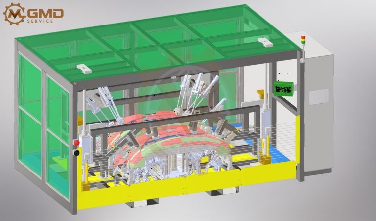
Ultrasonic Car Bumper Welding Machine Design for High-Precision Automotive Manufacturing
A specialized welding machine developed for automotive front...
View Portfolio